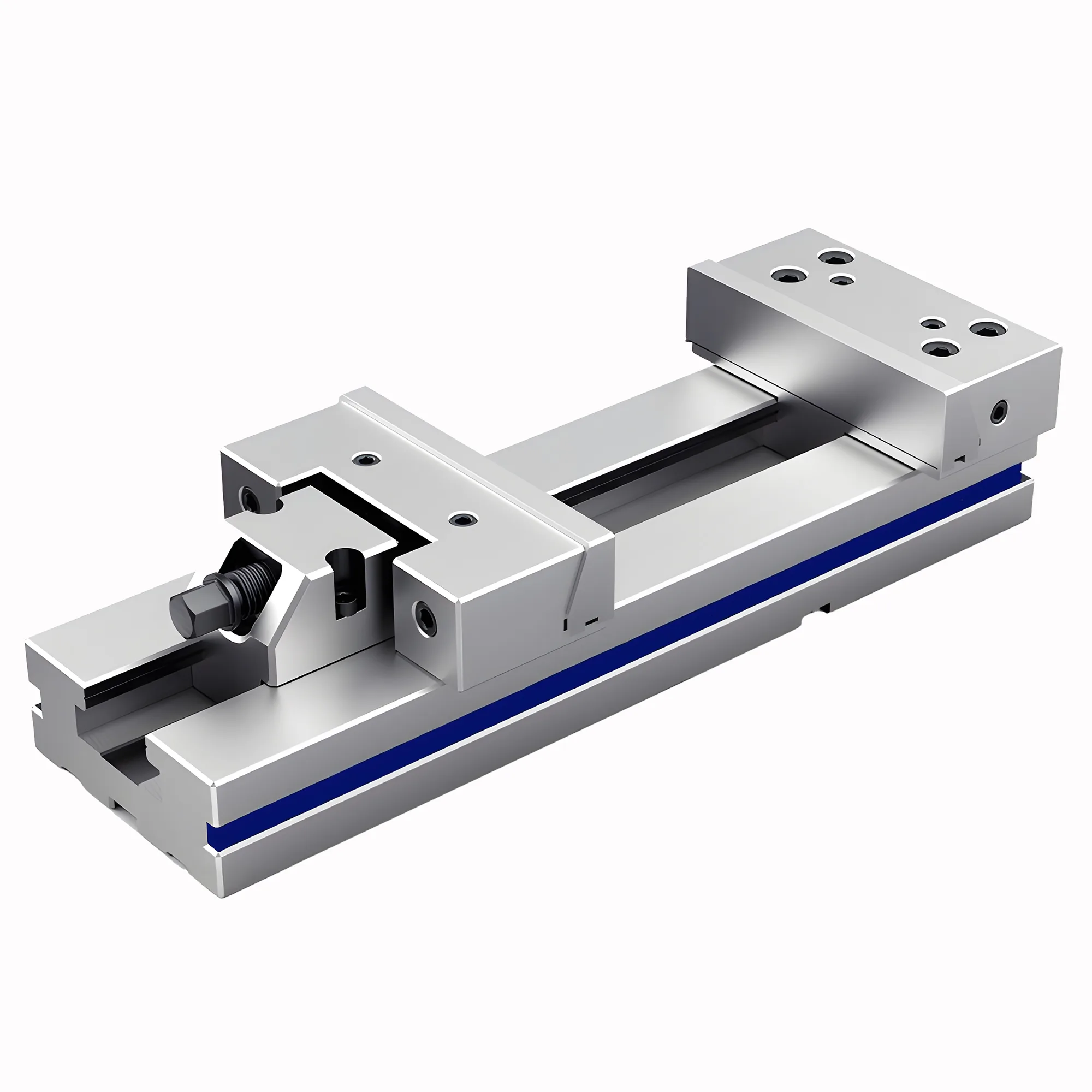
A properly trammed milling vise with correctly seated parallels holds the fixed-jaw sweep error below 0.005 mm over 150 mm — the threshold where step errors and angular workpiece lean become visible in finish cuts. Skipping or rushing either procedure introduces angular misalignment of 0.02–0.05 mm per 100 mm, which translates directly to tapered features, poor flatness, and re-work.
Quick Vise Setup Reference
| Problem / Goal | Primary Action | Expected Impact |
|---|---|---|
| Vise fixed jaw out of tram | Sweep fixed jaw with 0.001 mm indicator; tap vise body to correct | Angular error ≤ 0.005 mm per 150 mm jaw |
| Workpiece sitting high or tilted | Tap workpiece down onto parallels with a brass drift; recheck rattle | Seating error drops from 0.05 mm to < 0.01 mm |
| Parallel rattle after clamping | Clean T-slots and jaw faces; reclamp at 60–70% of rated torque | Parallel contact restored; workpiece lift eliminated |
| Chips under parallel | Blow out T-slot and jaw pocket; wipe with lint-free cloth | Seating error from chip eliminated (typical chip = 0.1–0.3 mm height error) |
| Angular step in finish pass | Re-tram vise; verify spindle tramming (spindle and vise errors add) | Step eliminated; flatness within 0.01 mm over 100 mm |
| Soft-jaw bore TIR excessive | Bore soft jaws after clamping to vise; never before | TIR reduced from 0.05–0.10 mm to < 0.01 mm |
Why Vise Tramming and Parallel Seating Matter
A vise that is mis-trammed by 0.03 mm over 150 mm introduces a 0.2 mm taper over a 1,000 mm traverse in production — an error that compounds across every feature on the part.
Vise tramming aligns the fixed jaw parallel to the machine X-axis (and the movable jaw parallel to the Y-axis) so that a workpiece clamped in the vise is oriented square to the spindle travel. Parallel seating ensures the workpiece bottom face contacts both parallels uniformly, holding the workpiece at a known, repeatable height and preventing tilt in the Z-axis.
These two procedures are linked: even a perfectly trammed vise fails to hold angular tolerances if the parallels are not fully seated. The vise body creates the X-Y angular reference; the parallels create the Z-height and tilt reference.
Dial test indicators (DTIs) with 0.001 mm resolution are the minimum instrument for tramming a precision vise used for toleranced work — 0.01 mm indicators are insufficient for this task.
In ISO 1101 terms, tramming controls the "angularity" of the clamping surface relative to the machine coordinate system. A mis-trammed vise projects this angularity error into every machined feature: bores are no longer perpendicular, shoulders are not square, and pocket floors are not flat.
Modular precision vises (such as the GT-series) have ground datum surfaces that reproduce tram within 0.005 mm when re-seated on a clean T-slot — but only if the seat surfaces and T-slot are clean. Toolmaker and sine vises require full indicator sweeping each time they are repositioned because they rely on the operator for angular alignment. See the modular vs sine vs toolmaker vise comparison for a full breakdown of body type accuracy and clamping force trade-offs.
Vise Tramming: Step-by-Step Procedure
Tools Required
- Dial test indicator (DTI): 0.001 mm resolution, 0.3 mm stroke minimum
- Magnetic indicator stand or test indicator arm in the spindle
- Brass or aluminum drift (for tapping the vise without marring)
- Precision level (optional, for initial coarse leveling)
- Torque wrench set to vise manufacturer's T-slot bolt torque spec (typically 40–60 N·m for M12 bolts)
Procedure
Step 1 — Clean the T-slot and vise base. Blow out the T-slot with compressed air. Wipe the T-slot top surface and vise base with a lint-free cloth. A single chip under the vise base produces a rigid tilt of 0.01–0.05 mm depending on chip thickness and vise footprint.
Step 2 — Mount the vise finger-tight. Drop the vise T-nuts into the T-slot and tighten the mounting bolts finger-tight only. The vise must be free to slide laterally without lifting.
Step 3 — Mount the indicator in the spindle. Fit the DTI into a test indicator holder or collet in the spindle. Position the indicator tip against the fixed jaw face (not the movable jaw) at the far left end of travel, typically 10–15 mm from the jaw edge. Preload approximately 0.2–0.3 mm.
Step 4 — Zero the indicator. Traverse the X-axis across the full jaw length. Record the total indicator reading (TIR). The zero is the reading at the left end; the reading at the right end shows the full angular error over the jaw width.
Step 5 — Correct in half-splits. If the error is 0.02 mm (right end higher), tap the right-rear corner of the vise body lightly with a brass drift until the indicator reads 0.01 mm (half of 0.02 mm). Then re-traverse. Repeat until the TIR is below 0.005 mm over the full jaw length.
Half-Split Correction
Tap the vise corner that is high. Each tap moves the vise a small amount. Always re-sweep after each tap to assess the correction — vise bodies respond non-linearly because the T-nuts act as pivot points. Three or four tap-and-measure cycles typically achieve 0.005 mm or better.
Step 6 — Torque the mounting bolts. Tighten the bolts to the manufacturer-specified torque in a diagonal sequence (left-front, right-rear, right-front, left-rear). After torquing, re-sweep the fixed jaw. Torquing can introduce a typical shift of 0.005–0.015 mm; if it exceeds 0.005 mm, loosen and correct again.
Step 7 — Final verification sweep. With bolts torqued, sweep the full jaw length. Record the result. For general milling, 0.010 mm TIR is acceptable. For toleranced work (bores, precision shoulders), target ≤ 0.005 mm.
Movable Jaw Indication Error
Avoid relying on the movable jaw face for precision tramming. The movable jaw is not a ground datum — it deflects 0.01–0.03 mm toward and away from the operator depending on clamping direction. Tramming against it introduces systematic error of 0.01–0.03 mm. Tram on the fixed jaw only for precision setups; the movable jaw face can serve as a coarse sanity check but not as a primary reference.
Parallel Selection and Seating Procedure
Choosing the Right Parallels
Matched, hardened parallel pairs with ≤ 0.002 mm thickness tolerance between the two pieces are required for repeatable multi-setup workholding — unmatched parallels produce step errors when the part is flipped or re-fixtured.
Parallels serve two functions: they elevate the workpiece above the jaws so the end mill has clearance below the workpiece, and they provide a flat, repeatable reference surface for the workpiece bottom face.
Standard ground parallels are made in matched pairs with thickness tolerance of ±0.001 mm per piece and ≤ 0.002 mm pair matching. For setups requiring workpiece height repeatability better than 0.01 mm, verify the pair with a micrometer before use.
Key selection criteria (for jaw type selection, see the vise jaw selection guide):
- Height: parallels should position the workpiece bottom face approximately 5–10 mm above the top of the vise jaw. Lower than 5 mm risks the end mill contacting the jaw; higher than 10 mm reduces effective clamping depth below the recommended 3× workpiece height minimum.
- Width: parallel width should be ≥ 60% of the jaw width to maximize contact area. Narrow parallels (< 40% jaw width) create a rocking fulcrum.
- Condition: check parallel faces with a precision straightedge or surface plate. Parallels with burrs, dings, or twist > 0.005 mm should be replaced.
Seating Procedure
Step 1 — Clean jaws and parallels. Wipe all four faces of each parallel (both flat sides and both edges) with a lint-free cloth. Clean the vise jaw faces and the bottom jaw pocket. A film of coolant residue between the parallel and jaw pocket contributes 0.002–0.005 mm of uncertainty.
Step 2 — Place parallels in the vise. Set the parallels symmetrically in the jaw pocket — equal distance from each jaw end, flush against the fixed jaw face.
Step 3 — Place the workpiece and close the vise lightly. Close the vise to light contact (no clamping pressure yet). Check that both parallels contact the workpiece bottom face — if one parallel rocks, check for chips or workpiece camber.
Step 4 — Test for rattle. With the vise at light clamping pressure, try to rock each parallel with a finger. Any rattle means the workpiece is bridging (bottom face is convex) or a chip is present. Open the vise, clean and restart.
Step 5 — Tap down and clamp. With light pressure, tap the workpiece down with a brass drift on the workpiece top face. The tap seats the workpiece onto the parallels by removing elastic springback in the vise jaw and workpiece. Re-test for rattle. Both parallels should be snug (no rattle) before final clamping.
Step 6 — Apply final clamping force. Clamp to the recommended force. For a precision modular vise on 1018 steel or 6061 aluminum workpieces, clamp force of 5–8 kN is typical for parts up to 50 mm wide. Over-clamping can bow the parallels off the jaw pocket floor — re-check rattle after full clamping.
The Rattle Test Standard
A parallel that rattles after clamping means the workpiece bottom face has lifted off the parallel surface — the vise is holding the workpiece by side friction only, and the Z-height reference is lost. The workpiece can shift by 0.02–0.10 mm in Z depending on chip size and workpiece weight. The tap-down tap-and-rattle check sequence is the established practice for precision setups; skipping it leaves Z-height drift of 0.02–0.10 mm undetected.
Common Error Sources and Correction
| Error Source | Symptom | Correction |
|---|---|---|
| Chips under vise base | Vise rocks; indicator TIR > 0.05 mm | Clean T-slot; re-mount |
| Tram using movable jaw | Feature angles wrong in Y-axis | Re-tram on fixed jaw |
| Parallel rattle ignored | Z-height varies 0.02–0.10 mm between setups | Tap down; verify no rattle before clamping |
| Unmatched parallels | Step height error when workpiece flipped | Use calibrated matched pairs; mike before use |
| Over-torqued mounting bolts | Tram shifts after torquing | Use torque wrench; re-sweep after torquing |
| Indicator preload insufficient | Reading unstable on jaw traverse | Set ~0.2–0.3 mm preload; use 0.001 mm DTI |
| Parallels too narrow | Workpiece rocks on parallels | Use parallels ≥ 60% of jaw width |
| Soft jaw not bored in-vise | TIR of bored profile > 0.02 mm | Always bore soft jaws with vise mounted and clamped |
Parallel error in the Z-axis (from unseated workpiece) is more common than tram error, yet operators check tram more often — both need equal attention in precision setups.
Diagnosing Tram vs. Parallel Seating Errors
When a machined feature is out of square or a step appears in a finish pass, the error source can be tram, parallel seating, or spindle tramming:
- Sweep the fixed jaw with the DTI. If > 0.010 mm: tram error. Correct and re-machine.
- Place a precision square on the workpiece after clamping. Check squareness of the vertical face to the machine table. If the square shows lean: parallel seating or workpiece face error.
- Indicate the spindle tram (sweep a ground disc in the spindle across the table). ASME B5.54 recommends spindle tramming tolerance of ≤ 0.005 mm per 300 mm. If the spindle is out, no amount of vise tramming will correct features machined perpendicular to the spindle axis. A similar systematic approach applies when indicating a four-jaw chuck: isolate the error source before correcting.
Spindle tramming and vise tramming errors add algebraically — a 0.005 mm spindle tram error and a 0.005 mm vise tram error combine to 0.010 mm total positional error on a workpiece feature.
Sine Vise and QKG-Series Precision Considerations
Sine vises (such as the QKG-series) introduce a third alignment dimension: the sine bar angle must be set with a calibrated gauge block stack, and the vise must be trammed both in X (jaw parallel to X-axis) and in Y (sine bar rotation axis parallel to Y-axis). This is a two-axis tram procedure:
- Tram the fixed jaw in X (standard procedure above).
- Indicate the sine bar pivot axis parallel to the machine Y-axis using a DTI in the spindle traversing in Y along the front edge of the sine bar.
- Set gauge block stack height = L × sin(θ), where L is the sine bar length (typically 100 mm or 200 mm) and θ is the required angle.
- Verify the stack height with a calibrated micrometer: for a 100 mm sine bar at 10°, L × sin(10°) = 100 × 0.1736 = 17.36 mm — use 17.00 mm + 0.36 mm stack (if available) or the nearest combination within 0.002 mm.
The gauge block height uncertainty δH propagates to angle uncertainty δθ ≈ (δH / L) × (180/π). With δH = 0.005 mm and L = 100 mm, the angle uncertainty is ≈ 0.003° — well within the tolerance of most angular features, which are typically ±0.1° or tighter. Angle error grows with shorter sine bar length, so use the longest available bar for tight-tolerance work.
Quick Verification Checklist Before First Cut
- Sweep fixed jaw: TIR ≤ 0.005 mm for precision work, ≤ 0.010 mm for general milling.
- Tap-rattle test: both parallels snug, no rattle under clamping force.
- Workpiece-top indicator scan: indicate the top face of the workpiece after clamping. Any reading above ± half the workpiece face flatness spec indicates seating error — open, clean, reclamp.
- Vise bolt torque: check with a torque wrench before the first part. Re-sweep after torquing.
- Spindle tram: if any feature must be square to the table, verify spindle tram per ASME B5.54 (≤ 0.005 mm per 300 mm).
- Parallel height clearance: verify the end mill will not strike the parallel or vise jaw at full depth. Use a Z-height probe or careful manual Z-approach.
Running through the 6-point verification checklist adds 5–10 minutes per setup but eliminates the most common source of re-work on first-off parts — a workpiece that passes inspection in the first operation only to fail in the second because the vise was re-mounted without re-tramming.
Tram the fixed jaw; seat the parallels; verify both before cutting.
For precision milling, tram the fixed jaw to ≤ 0.005 mm TIR, seat parallels with the tap-down rattle check, and run the 6-point checklist before the first cut. Both procedures together take under 15 minutes and prevent the most common source of angular and Z-height errors in milled parts.
What indicator resolution is needed for vise tramming?
A 0.001 mm resolution dial test indicator (DTI) is the minimum for precision vise tramming. A 0.01 mm indicator cannot resolve the 0.005 mm target tolerance reliably, since one graduation equals the entire tolerance band. Use a DTI with at least 0.3 mm stroke and approximately 0.2–0.3 mm preload against the fixed jaw face.
How tight should a trammed vise be — what is the acceptable TIR?
For general milling, ≤ 0.010 mm TIR over the full jaw length is acceptable. For toleranced features (precision bores, shoulders, pocket floors requiring flatness < 0.01 mm), target ≤ 0.005 mm TIR. Tighter than 0.003 mm is rarely achievable in production without also verifying spindle tramming, which adds independently.
Why do parallels rattle after clamping, and what does it mean?
Parallel rattle after clamping means the workpiece bottom face is not in full contact with both parallels — the vise jaws are holding the part by friction alone, with no Z-height reference. Common causes include chips on the jaw pocket floor, a convex workpiece bottom face, or parallel width that is too narrow to support the workpiece. Tap the workpiece down onto the parallels with a brass drift before applying final clamping torque, and re-test for rattle.
Can vise tramming errors and spindle tramming errors be separated?
Yes. Indicate the spindle tram separately by sweeping a ground flat disc in the spindle across the machine table — this measures spindle-to-table squareness independent of the vise. Then tram the vise fixed jaw with the DTI. The two errors add algebraically: a 0.005 mm spindle error plus a 0.005 mm vise error gives 0.010 mm total angular error on a machined feature. Both must be within spec for precision work.
How often should a vise be re-trammed?
Re-tram whenever the vise is unbolted and remounted, after a heavy crash, or after any machining event that may have shifted the vise (heavy interrupted cuts, tapping operations, or T-slot contamination). A modular precision vise with datum keys re-seats within 0.005 mm without re-tramming if the T-slot is clean; a standard vise without datum keys requires indicator tramming every remount.
Sources
- ISO 1101:2017 — Geometrical tolerancing: tolerances of form, orientation, location and run-out
- ASME B5.54-2005 — Methods for Performance Evaluation of CNC Machining Centers
- Machinery's Handbook 31st Edition, "Jigs, Fixtures, and Workholding" chapter
- Precision Vise Application and Setup Guide — Kurt Manufacturing