A four-jaw independent chuck can achieve ≤0.01 mm TIR concentricity on turned stock when indicated correctly — but reaching that accuracy requires a systematic half-correction technique, not guesswork. This article covers the complete dial indicator setup procedure, the specific steps for holding eccentric and irregular parts, and the common errors that add typically 0.05–0.15 mm of unnecessary runout per job (varies by chuck condition and technique).
Quick Four-Jaw Chuck Setup Reference
| Problem / Goal | Primary Action | Expected Impact |
|---|---|---|
| Initial rough centering | Measure workpiece diameter, set jaw-to-jaw gap to match before mounting | Reduces first-indicator reading error by 50–70% |
| High TIR on first indicator check (>1 mm) | Rotate work to find high point, apply half-correction to opposite jaw pair | Converges to <0.1 mm TIR in 2–3 iterations |
| Final TIR not reaching target (<0.02 mm) | Switch to 0.001 mm resolution indicator; tap with soft mallet not jaw screw | Achieves ≤0.01 mm TIR in rigid setups |
| Eccentric part slipping during setup | Pre-load opposing jaw pair before indicating; use soft jaws or copper shim | Eliminates creep during final tightening by ~80% |
| Repeatability lost after part removal | Scribe reference marks on jaw and chuck body at final position | Returns to within 0.02–0.05 mm on re-setup |
Why Four-Jaw Setup Accuracy Matters
Among common lathe chucks, the four-jaw independent chuck is the standard tool for deliberate off-center holding and sub-0.01 mm concentricity on non-round stock — faceplate setups and four-jaw self-centering (K12) chucks serve narrower niches. A three-jaw scroll chuck typically runs ~0.05–0.15 mm TIR on used equipment (varies by chuck age and condition); a four-jaw indicated to 0.01 mm is 5–15 times more accurate under comparable conditions.
The practical stakes are real. Facing a 50 mm diameter shaft that is 0.1 mm off-center removes an asymmetric 0.2 mm pass: one side cuts 0.3 mm deep, the opposite side cuts 0.1 mm or less. On thin-walled parts, this imbalance causes chatter, taper, and in worst cases bending the workpiece against the spindle axis. Each 0.01 mm of runout at the chuck translates to the same 0.01 mm diameter error at the cutting zone, assuming zero tool deflection in a rigid setup.
The four-jaw chuck carries a performance cost: setup time typically runs 3–10 minutes for an experienced machinist, versus under 30 seconds for a three-jaw chuck. For a full comparison of when to choose a three-jaw versus four-jaw chuck, see the 3-jaw vs 4-jaw lathe chuck selection guide. The setup cost is justified for precision bores, one-off parts ground on the OD, castings, forgings, and any part where concentricity tolerance is tighter than 0.05 mm TIR.
What Determines Achievable TIR
The minimum achievable TIR is set by three factors acting in series:
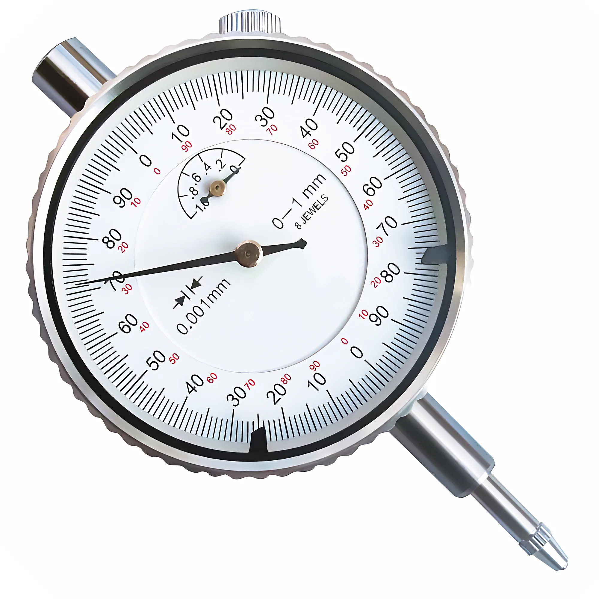
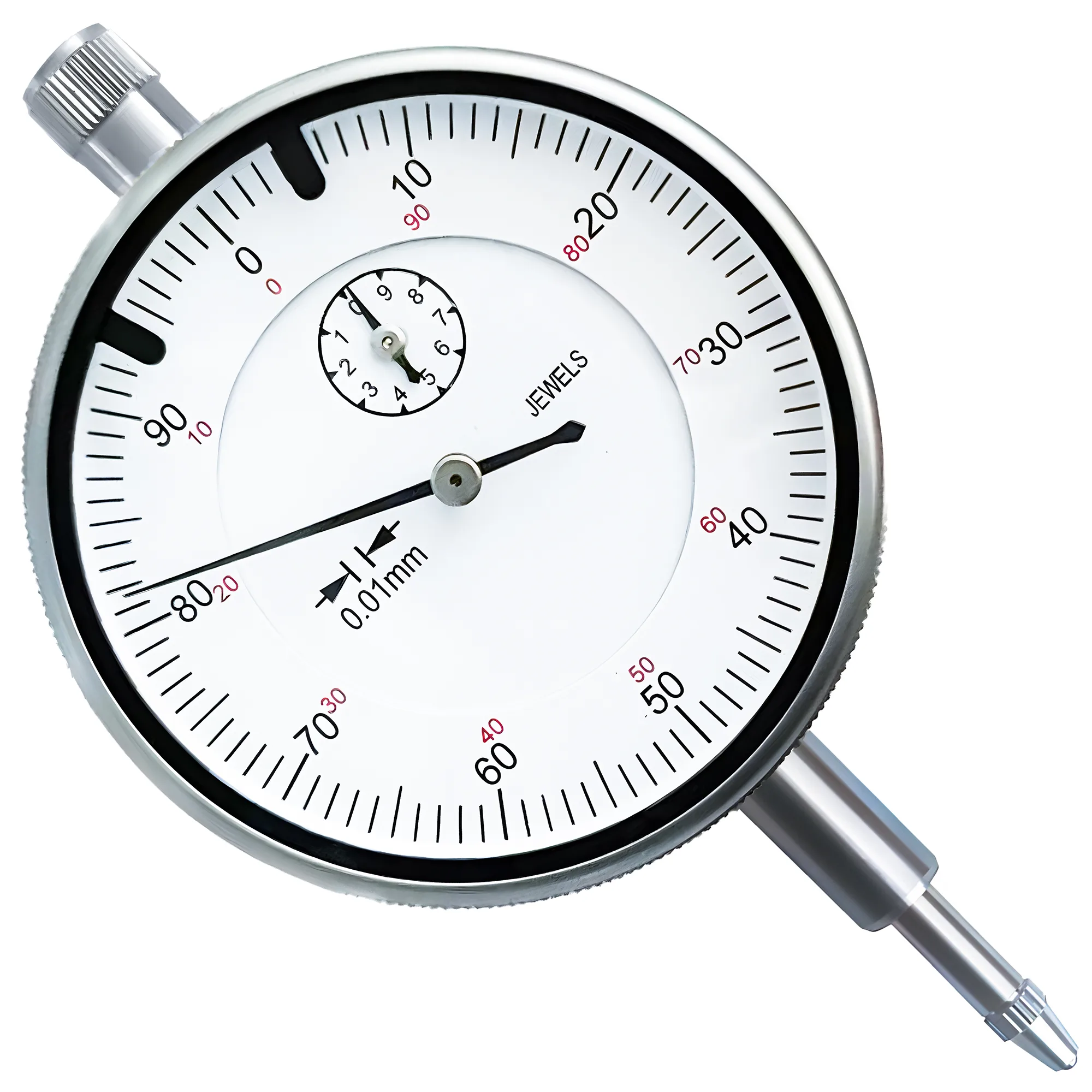
- Indicator resolution and accuracy — A 0.01 mm graduation indicator (ISO 463 / JIS B7503 general resolution: 0.01 mm) limits final reading to ±0.005 mm at best. For sub-0.01 mm targets, use a 0.001 mm resolution indicator (ISO 463 / JIS B7503 fine resolution: 0.001 mm). For a full comparison of indicator types by application, see the micrometers vs dial indicators selection guide.
- Chuck jaw backlash and condition — Worn jaws with >0.03 mm of T-slot play give the screw a dead zone that makes micro-corrections unpredictable.
- Workpiece surface condition — Scale, burrs, and OD taper all create false high spots on the indicator. Indicating on a ground or turned surface reduces false readings by eliminating surface-variation interference.
ISO 463 is the international standard governing dial indicator mechanical accuracy classes, stroke, and graduation intervals; it defines the 0.001 mm and 0.01 mm grades used to select the right indicator for a given TIR target.
The Half-Correction Dial Indicator Technique
The half-correction method is the standard approach for converging to zero TIR in the minimum number of jaw adjustments. The half-correction technique works by moving the workpiece exactly half the total indicated runout on each pass, so the center approaches the spindle axis geometrically rather than by trial and error.
Step-by-Step Procedure
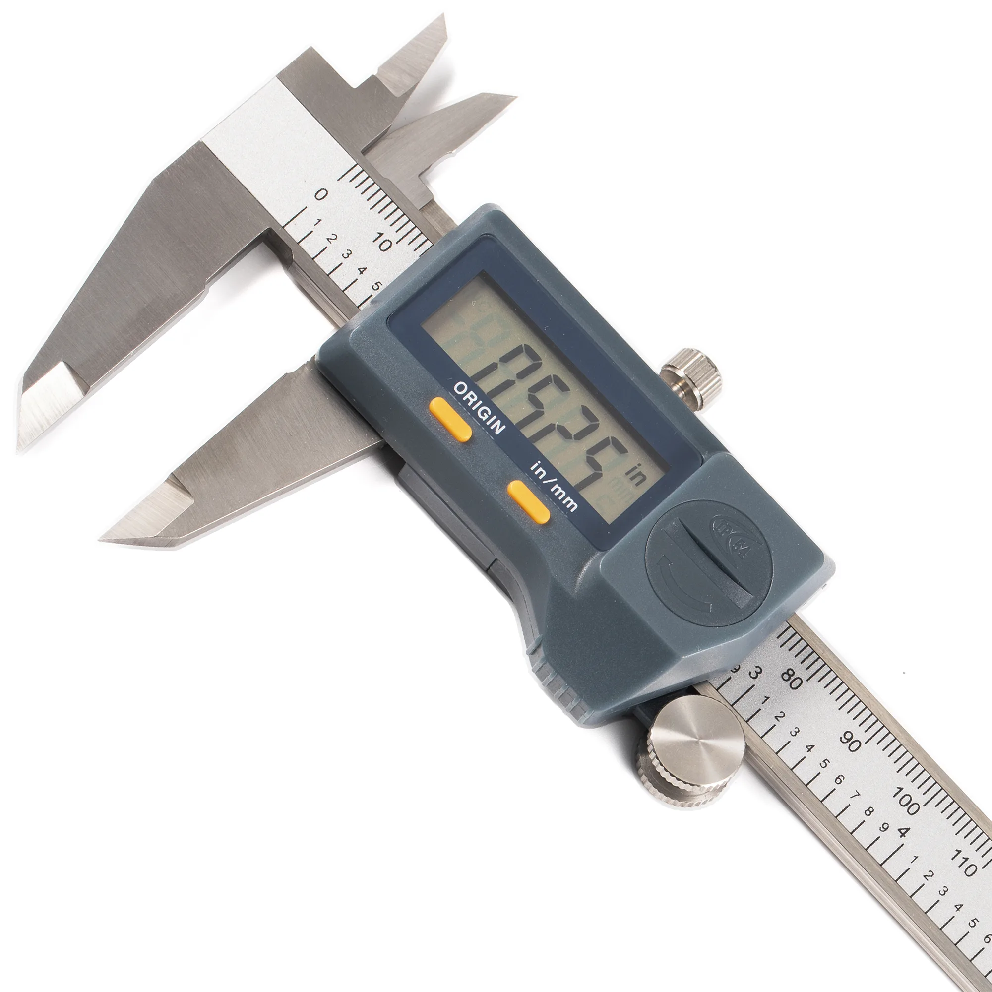
Step 1 — Premount estimation. Before mounting, measure the workpiece diameter with a caliper. Adjust opposing jaw pairs so the gap between them equals the workpiece diameter. This rough pre-set typically brings the first indicator reading under 1 mm, cutting the number of correction passes needed by 40–60%.
Step 2 — Mount and snug. Insert the workpiece and tighten all four jaws to light contact — enough to hold the part but not enough to prevent sliding. The part must be moveable under jaw force.
Step 3 — First indicator reading. Mount a 0.01 mm graduation dial indicator on the tool post or a magnetic stand. Contact the indicator stylus on the workpiece OD at roughly mid-length. Rotate the spindle by hand (never power) through 360°. Record the total indicated runout (TIR = maximum reading minus minimum reading, not the algebraic span).
Step 4 — Locate the high point. Rotate until the indicator reads its maximum. The high point is the jaw furthest from the spindle axis. The high-point jaw is the one to push away from; the low-point jaw is the one to pull toward.
Step 5 — Apply half-correction. The correction move is: loosen the high-point jaw by approximately TIR/2, then tighten the diametrically opposite (low-point) jaw by the same amount. The goal is not to measure the jaw movement in millimeters but to watch the indicator: after loosening the high jaw, the reading should drop by half the original TIR.
Step 6 — Rotate 90° and check the second axis. After correcting the first axis, rotate 90° to find the high point in the perpendicular jaw pair. Apply the same half-correction to that pair.
Step 7 — Iterate. Repeat Steps 3–6. On clean, round stock, two to three full correction cycles typically converge to <0.02 mm TIR. A third cycle with a 0.001 mm indicator brings most setups to ≤0.008 mm TIR.
Step 8 — Final tighten. Tighten all four jaws in a star pattern (1–3–2–4 or diagonally opposite pairs) to equalize clamping force. Recheck the indicator after final tightening — in typical shop conditions, the final tighten can shift the part by ~0.005–0.02 mm if jaw pressure is uneven.
Best Practice
Tap the workpiece gently with a dead-blow or soft mallet at the high point just before the final correction tighten. The tap seats the workpiece against the jaw faces and eliminates the 0.005–0.015 mm shift that occurs when the screw thread self-centers under load. This one step routinely removes the last 30–50% of residual TIR.
Why Half-Correction Works Faster than Full-Correction
A full-correction attempt (moving the work the entire TIR distance) typically overshoots because jaw screw mechanics are not linear: the first thread of engagement moves the work more per degree of rotation than later threads under load. Half-correction undershoots by design, so the approach is always from one side — this eliminates the oscillation that occurs when full-correction alternately overshoots in each axis.
Eccentric and Irregular Part Holding
Holding non-round parts — castings, weld fabrications, forgings, parts requiring an off-center bore — requires adapting the indicating procedure to the part geometry.
Eccentric Turning: Off-Center Setup
To bore a hole whose center is offset from the OD center by a known distance E:
- Indicate the OD to zero TIR as described in Section 02.
- Record the indicator position (angular and radial) at that zero-TIR position.
- Without touching the workpiece, offset one jaw pair by exactly 2E (twice the eccentricity) using the dial indicator as a reference — loosen one jaw by 2E and tighten the opposite by 2E, watching the indicator.
- Re-snug the other pair to maintain clamping. The OD now runs eccentric by E from the spindle axis, meaning the spindle axis passes through the desired bore location.
For eccentricities up to 5 mm, the four-jaw independent chuck provides direct, single-indicator control without requiring an offset turning fixture. Larger eccentricities (>10 mm) may require a purpose-built offset plate or faceplate mounting to preserve jaw engagement depth.
Irregular and Asymmetric Parts
Castings and forgings present an irregular OD that the indicator reads as a combination of out-of-center and surface variation. The standard approach is to scribe or Dykem a reference circle on the casting's bore centerline using a height gauge before mounting, then indicate off the scribed circle rather than the raw OD.
When no reference surface exists:
- Mount the part loosely and take a full 360° indicator reading on the best available surface.
- Note and discount obvious surface defects (porosity, scale bumps) by marking them with chalk — exclude those angular positions from the TIR calculation.
- Indicate to the average best-surface TIR rather than absolute zero, accepting 0.05–0.10 mm as typical for rough castings.
For thin-walled parts (wall ≤ 3 mm), excessive clamping force at final tightening can deform the bore by 0.01–0.05 mm, negating the indicating effort. DIN 6350 specifies lathe-chuck and jaw-form geometry, ensuring interchangeable jaw sets across manufacturers; for clamping-force limits against thin walls, soft jaw inserts or copper shim stock distribute clamping force and reduce deformation by 60–80% in typical workshop conditions, and the formula-based limits follow from the workholding clamping force calculation guide. For the formula-based approach to calculating clamping force against cutting loads, see the workholding clamping force calculation guide.
Avoid This
Avoid using a four-jaw chuck as an improvised vise by tightening only two opposing jaws. This creates a two-point pinch that concentrates all clamping force on a narrow jaw face, producing typically 0.1–0.5 mm deformation in cast iron parts (varies by wall thickness and jaw contact area) and OD marking on steel. All four jaws should bear load to distribute clamping pressure.
Parameter Reference and Indicator Selection
Indicator Selection by Target TIR
| Target TIR | Indicator Resolution | Standard Reference | Typical Application |
|---|---|---|---|
| ≤0.10 mm | 0.01 mm (general) | ISO 463 / JIS B7503 | Production turning, rough setups |
| ≤0.02 mm | 0.01 mm (general) | ISO 463 / JIS B7503 | Standard precision turning |
| ≤0.01 mm | 0.001 mm (fine) | ISO 463 / JIS B7503 | Precision boring, ground shaft work |
| ≤0.005 mm | 0.001 mm (fine) with calibrated indicator | ISO 463 Grade 0 | High-precision, gauge-quality setups |
ISO 463 is used for dial indicators because it defines the accuracy grade, resolution graduations, and stylus force requirements that determine whether a given indicator is reliable at the target resolution. JIS B7503 is the Japanese equivalent used on Japanese-built lathes and measuring equipment.
Typical Setup Times by Complexity
| Part Type | First TIR (pre-correction) | Setup Time (experienced) | Final TIR Achievable |
|---|---|---|---|
| Turned round bar | 0.3–1.0 mm | 3–5 min | ≤0.008 mm |
| Ground shaft | 0.1–0.5 mm | 2–4 min | ≤0.005 mm |
| Rough casting (rough OD) | 1.0–5.0 mm | 8–15 min | ≤0.05–0.1 mm |
| Eccentric bore offset 3 mm | N/A (deliberate offset) | 5–8 min | ≤0.015 mm offset accuracy |
| Irregular forging | 2.0–8.0 mm | 10–20 min | ≤0.08 mm |
Common Errors and Their TIR Cost
| Error | TIR Added | Prevention |
|---|---|---|
| Indicating on a burred OD | +0.05–0.20 mm | Deburr before indicating; use stone on sharp edges |
| Full-correction overshoot | +0.02–0.10 mm per axis | Use half-correction; watch indicator, not jaw movement |
| Uneven final tighten (one jaw first) | +0.005–0.02 mm | Star-pattern tighten; recheck indicator after |
| Soft jaw not fully engaged in T-slot | +0.03–0.15 mm | Verify jaw engagement depth ≥ 75% of slot length |
| Indicating near the jaw face instead of mid-length | +0.01–0.05 mm | Position indicator at 40–60% of exposed part length from chuck face |
Repeatability Marking
After achieving the target TIR, scribe a witness mark across one jaw face and the chuck body with a sharp scriber. If the part is removed and re-mounted to the same jaw position and scribed mark alignment, typical return accuracy is 0.02–0.05 mm TIR — sufficient for most secondary operations without full re-indicating.
Summary
Indicate to half-correction, two axes, three iterations for ≤0.01 mm TIR.
The four-jaw half-correction technique — locating the high point, correcting by TIR/2 in each axis pair, iterating 2–3 times — consistently delivers ≤0.01 mm TIR on turned stock when using a 0.001 mm resolution indicator (ISO 463 / JIS B7503 fine grade). For eccentric setups, zero the OD first, then apply the known eccentricity offset as a secondary dial-indicator measurement. Final tightening in a star pattern is critical: skipping it can add ~0.005–0.02 mm of shift in typical setups and undo the last correction pass. A dead-blow tap at the high point before the final tighten removes the last 30–50% of residual runout in most setups.
Sources
- ISO 463:2006 — Dial gauges: design and metrological characteristics
- JIS B7503:2011 — Dial gauges (Japanese Industrial Standard)
- DIN 6350 — Lathe chuck jaws: forms and dimensions
- Machinery's Handbook, 31st Edition — Industrial Press
- Boothroyd & Knight, Fundamentals of Machining and Machine Tools, 3rd ed. — CRC Press
How do I indicate a four-jaw chuck to zero runout?
Mount a 0.01 mm resolution dial indicator on the tool post touching the workpiece OD. Rotate by hand to find the high point, then loosen that jaw and tighten the opposite jaw by half the total indicated runout (TIR). Repeat on the 90° axis. Two to three iterations typically achieve ≤0.02 mm TIR; switching to a 0.001 mm indicator for the final pass brings most setups to ≤0.01 mm.
What is the half-correction method for four-jaw chucks?
The half-correction method moves the workpiece by exactly half the TIR on each correction pass. Move by the full TIR and you overshoot due to non-linear jaw screw mechanics; move by half and you approach zero from one side, converging in 2–3 passes rather than oscillating. The technique applies the same half-TIR correction to both the X-axis and Y-axis jaw pairs in sequence.
How long does it take to set up a four-jaw chuck?
An experienced machinist typically takes 3–5 minutes to indicate turned round bar to ≤0.02 mm TIR, and 8–15 minutes for rough castings where surface variation limits final accuracy to 0.05–0.10 mm. Initial rough centering (pre-setting jaw gaps to the workpiece diameter) reduces first-pass TIR by 50–70% and cuts total setup time by 1–2 minutes.
Can a four-jaw chuck hold eccentric parts?
Yes. Indicate the OD to zero TIR first, then offset one jaw pair by twice the desired eccentricity (2E) while watching the indicator — the spindle axis will then pass through the eccentric bore location. This direct method works for eccentricities up to about 5 mm; larger offsets may require a faceplate or offset turning fixture to maintain adequate jaw engagement depth.
What dial indicator resolution do I need for four-jaw setup?
Use a 0.01 mm graduation indicator (ISO 463 / JIS B7503 general grade) for setups targeting ≤0.05 mm TIR — this covers most production turning. For targets ≤0.01 mm, switch to a 0.001 mm resolution indicator (ISO 463 fine grade); the 0.01 mm indicator cannot resolve the corrections needed in the final passes and will typically leave ~0.010–0.015 mm of residual runout.