Outside micrometers measure absolute dimensions to ±0.004 mm (0-50 mm range, DIN 863) with 0.001 mm or 0.01 mm graduation. Dial indicators measure relative displacement — metric fine models resolve 0.001 mm over a 1 mm range (ISO 463), while general models resolve 0.01 mm over 10 mm. Digital indicators add USB data output and ±0.005 mm accuracy. This guide covers selection by accuracy class, reading technique, and when to use each type.
For a complete overview of precision measurement tools including calipers, gauge blocks, and environmental control, see the precision measurement complete guide. While calipers handle rough verification, micrometers and dial indicators cover the critical range between +/-0.02mm and single-micron deviations. Micrometers measure absolute dimensions; dial indicators measure relative displacement from a datum. Understanding the distinction and the accuracy classes available within each category prevents overspending on unnecessary precision and underspending where it matters.
Outside Micrometer Accuracy Classes and Ranges
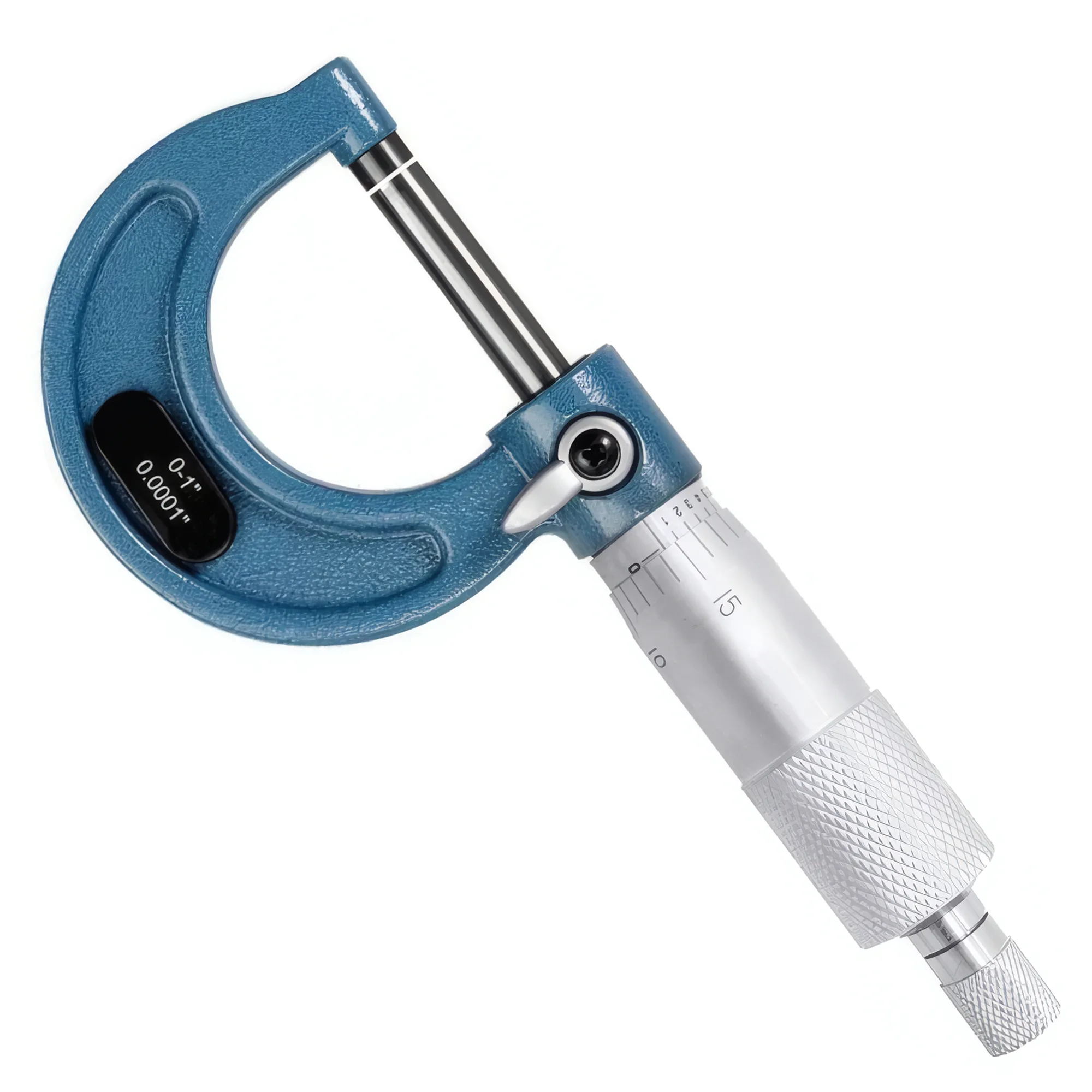
Outside micrometers follow a standard 25mm measuring span per instrument. Each range has a defined accuracy class that determines how close the reading will be to the true dimension. Outside micrometers in the 0-50 mm range deliver ±0.004 mm accuracy per DIN 863 / ISO 3611 when verified against gauge blocks at 20°C reference temperature (ISO 1).
Standard graduation (0.01mm / 0.001") micrometers read from the thimble and sleeve scales. They suit general machining verification where tolerances are +/-0.02mm or wider. The 0.01mm graduation is sufficient for most turning and milling operations.
Fine graduation (0.001mm / 0.0001") micrometers add a vernier scale on the sleeve, resolving an additional decimal place. Fine-graduation (0.001 mm) micrometers are the preferred choice when grinding tolerances or gage pin verification demand single-micron discrimination, even though their stated accuracy matches standard 0.01 mm models.
Imperial micrometers follow the same principle with 1-inch spans. A 0-1" micrometer with 0.001" graduation has accuracy of +/-0.00015", while 2-3" and 3-4" ranges relax to +/-0.0002". Fine graduation models at 0.0001" maintain the same accuracy but allow the operator to resolve ten-thousandths of an inch -- critical for aerospace and medical component inspection.
| Range | Graduation | Accuracy | Typical Application |
|---|---|---|---|
| 0-25mm (0-1") | 0.01mm (0.001") | +/-0.004mm (+/-0.00015") | General machining, turning |
| 0-25mm (0-1") | 0.001mm (0.0001") | +/-0.004mm (+/-0.00015") | Grinding, final inspection |
| 25-50mm (1-2") | 0.01mm (0.001") | +/-0.004mm (+/-0.00015") | Shaft diameters, stepped features |
| 50-75mm (2-3") | 0.01mm (0.001") | +/-0.005mm (+/-0.0002") | Large bore work, flange OD |
| 75-100mm (3-4") | 0.01mm (0.001") | +/-0.005mm (+/-0.0002") | Heavy turning, large components |
Ratchet Stop Discipline
Close the micrometer using the ratchet stop rather than the thimble directly. The ratchet limits measuring force to approximately 5-10N regardless of operator hand strength. Bypassing the ratchet can apply 20-50N, elastically deforming both the workpiece and the micrometer frame. On a 25mm steel part, 50N of excess force compresses the contact zone by approximately 1-2 um -- enough to push a reading outside tolerance on a +/-0.005mm feature.
Dial Indicator Types -- Fine, General, and Ultra-Fine
Dial indicators measure displacement rather than absolute dimensions. The spindle moves linearly against a spring, and the gear train amplifies this motion to rotate the dial needle. Dial indicators are the standard instrument when the measurand is deviation from a reference (runout, parallelism, alignment) rather than an absolute dimension, because their spring-loaded spindle and amplification gear train resolve micron-level displacement that micrometer contact geometry is not designed to replicate in dynamic setups.
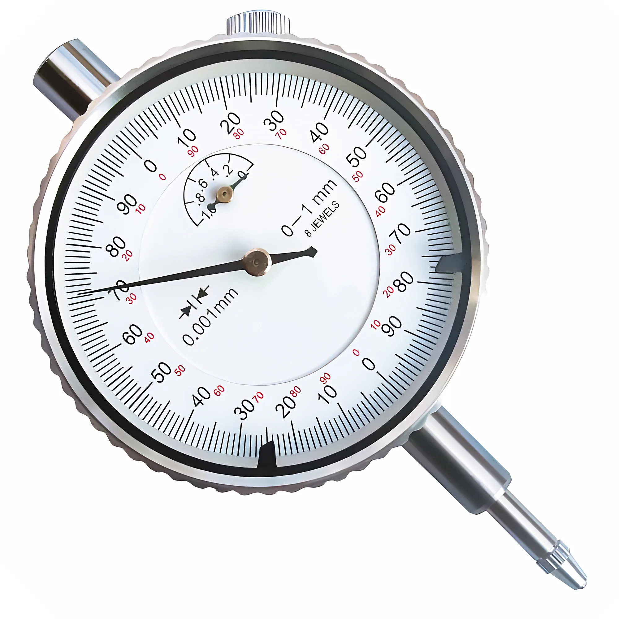
Metric fine indicators (0.001mm graduation) resolve individual microns across a 0-1mm range. Built with jewel bearings for friction-free spindle travel and sealed dust caps for shop floor protection. The 58mm dial face with bezel locking allows zero-setting at any point. Metric fine 0.001 mm indicators (per ISO 463 / JIS B7503) are the standard instrument for spindle runout verification on ground shafts, where 1-2 µm discrimination determines whether a TIR check passes or fails.
Metric general indicators (0.01mm graduation) typically cover larger ranges of 0-3mm, 0-5mm, or 0-10mm. The coarser graduation trades resolution for travel -- a 10mm range indicator can track a milling vise alignment across its full stroke. Steel body construction and jewel bearings provide durability for daily shop use.
Inch ultra-fine indicators (0.0001" graduation) deliver the highest analog resolution available, with a compact 0-0.050" measuring range. Jewel bearings, sealed dust cap, and aluminum alloy body keep weight low for magnetic base setups. Inch ultra-fine 0.0001" (2.5 µm) indicators are preferred for machine tool acceptance testing per the ISO 230 series, because the 2.5 µm resolution captures spindle and slide deviations that coarser indicators average out.
Inch fine indicators (0.0005" graduation) balance resolution against range, covering 0-0.250", 0-0.500", or 0-1.000" of travel. External tolerance markers and bezel locking simplify go/no-go inspection setups.
| Indicator Type | Graduation | Range | Bearings | Best Application |
|---|---|---|---|---|
| Metric Fine | 0.001mm | 0-1mm | Jewel | Runout, concentricity, gage R&R |
| Metric General | 0.01mm | 0-3 / 0-5 / 0-10mm | Jewel | Alignment, setup, TIR checks |
| Inch Ultra-Fine | 0.0001" | 0-0.050" | Jewel | Bearing bores, acceptance testing |
| Inch Fine | 0.0005" | 0-0.250" to 0-1" | Standard | Setup verification, go/no-go checks |
Digital vs Analog Indicators
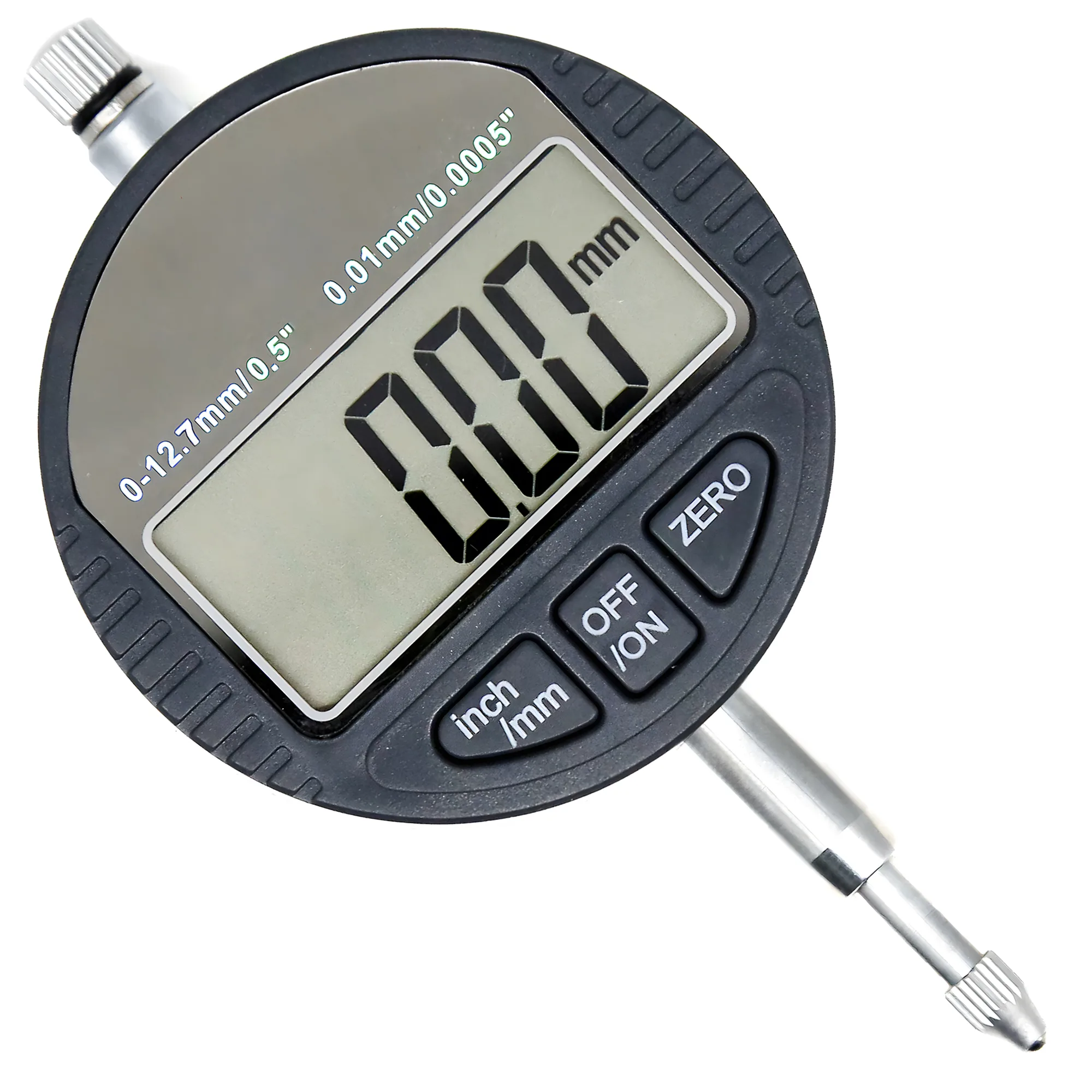
Digital dial indicators replace the mechanical gear train with an electronic encoder and LCD display. Digital indicators with 0.001 mm resolution and ±0.005 mm accuracy typically cost 40-80% more than equivalent analog models, but eliminate manual transcription error in SPC workflows through USB data output.
Digital advantages: Zero-reset at any position eliminates mental arithmetic. One-button metric/inch switching suits shops running mixed-unit drawings. Serial data output (USB) enables SPC logging without manual transcription. Preset value functions allow quick tolerance checking. Resolution options include 0.01mm (0.0005") for general use and 0.001mm (0.00005") for precision applications.
Digital limitations: Battery dependency (CR2032, typically 1-2 years of use). Electronics are more sensitive to coolant ingress than sealed analog mechanisms. Display can be difficult to read in bright sunlight or from oblique angles. Cost is 40-80% higher than equivalent analog models.
Analog advantages: No batteries to fail. Needle movement provides intuitive directional feedback -- you can see the indicator "breathing" as it approaches a high point during runout checks. Jewel bearing mechanisms have indefinite service life with proper care. Lower cost per unit of resolution.
For SPC-driven quality systems, digital indicators with data output justify their cost through eliminated transcription errors and automated data collection. For setup and alignment work where the operator watches the needle in real time, analog indicators remain preferred by most experienced machinists.
For day-to-day caliper handling alongside micrometer and indicator workflows, see the digital caliper care guide.
When to Choose Each Instrument
The fundamental question is whether you need an absolute dimension (micrometer) or a deviation measurement (indicator). Choose a micrometer when the drawing calls out a numerical dimension with tolerance; choose a dial indicator when the requirement is geometric (runout, parallelism, alignment) and the readout is a deviation from a reference.
✦ Micrometers Best For
- Absolute dimensional measurement (shaft diameter, wall thickness)
- Final inspection of machined features to drawing tolerances
- Verification against specific numerical dimensions
- Gage pin and standard verification
✦ Dial Indicators Best For
- Relative displacement measurement (runout, alignment, parallelism)
- Machine setup and workholding verification
- In-process monitoring during machining
- Comparative measurement against a master reference
Resolution matching by task:
- CNC lathe setup alignment: Metric general indicator, 0.01mm, typical 0-10mm range -- needs travel to cover chuck jaw runout
- Grinding final inspection: Outside micrometer, 0.001mm graduation, +/-0.004mm accuracy
- Spindle runout check: Metric fine indicator, 0.001mm, 0-1mm range -- needs micron-level resolution
- Incoming material verification: Outside micrometer, 0.01mm graduation -- speed matters more than last-decimal precision
- Bearing bore inspection: Inch ultra-fine indicator, 0.0001", 0-0.050" range, or digital indicator at 0.001mm resolution
- Surface plate height comparison: Digital indicator with data output for SPC logging
Reading Techniques and Error Prevention
Measurement errors from technique typically exceed instrument error by 5-10x. Two operators using the same micrometer on the same part routinely disagree by 3-5 µm in shop-floor conditions unless both follow ratchet-stop discipline, parallax-free reading, and 30-second thermal stabilization.
Micrometer reading errors:
- Parallax on vernier scale: Read the vernier with your line of sight perpendicular to the thimble. Viewing at an angle shifts the apparent alignment by 0.001-0.002mm. Fine-graduation (0.001mm) micrometers with a vernier scale are particularly sensitive to this.
- Thermal expansion: Body heat transfers to the frame at approximately 1 um per 10 seconds of bare-hand contact on a 0-25mm steel micrometer. Hold by the insulated plates only. For sub-5 um accuracy, use a micrometer stand and allow 30 seconds of thermal stabilization after each handling.
- Zero error: Check the zero point against a gauge block before each measurement session. A 0-25mm micrometer should read exactly zero with clean faces lightly closed via the ratchet stop. Micrometers 25-50mm and above should be checked against their supplied setting standard.
Indicator reading errors:
- Cosine error: If the indicator spindle is not perpendicular to the surface being measured, the reading is shorter than the actual displacement by a factor of cos(angle). A 5-degree misalignment reduces a 0.100mm reading to 0.0996mm -- small but relevant at 0.001mm resolution.
- Hysteresis: Reversing the direction of spindle travel introduces a small dead zone (typically 2-5 um on quality indicators) due to gear backlash. Always approach the measurement point from the same direction, or record the full range of needle travel rather than a single-direction reading.
- Stem deflection: Long stems on magnetic base setups flex under vibration. Keep the indicator stem as short as possible and lock all joints firmly. A 200mm stem deflects approximately 10x more than a 100mm stem under the same vibration.
Technique errors — parallax, thermal drift, cosine misalignment, and hysteresis — typically account for more measurement uncertainty than instrument grade, making consistent handling protocol as important as instrument selection.
Common Calibration Mistake
Do not assume a new instrument is accurate out of the box. Factory calibration certificates verify accuracy at the time of manufacture, but shipping shock can shift the zero or damage the mechanism. Verify every new micrometer against gauge blocks and every new indicator against a known displacement standard before putting it into service. Document the as-received condition -- this protects both the user and the supplier if a discrepancy is found.
Maintenance, Storage, and Calibration Intervals
Instrument longevity depends more on daily handling habits than on build quality. Micrometers require annual recalibration per DIN 863 / ISO 3611 (or quarterly in high-use production), while dial indicators require annual verification per ISO 463 / JIS B7503 to remain traceable to national length standards.
Micrometers: Clean measuring faces with a lint-free cloth after every use. Store with faces slightly open (0.5-1mm gap) to prevent contact corrosion between carbide and steel surfaces. Apply a thin film of instrument oil to the spindle threads monthly. Recalibrate annually per DIN 863 / ISO 3611, or quarterly in high-use production environments. Replace carbide faces when wear causes flatness to exceed 0.6 um or parallelism to exceed 1.0 um.
Analog indicators: Retract the spindle fully before storing to prevent spring fatigue. Keep dust caps sealed in dirty environments. Jewel bearings require no lubrication but are brittle -- a single drop onto a concrete floor can crack the jewels and ruin the instrument. Recalibrate annually per ISO 463 / JIS B7503. Check repeatability by approaching the same point from the same direction ten times -- variation should not exceed one graduation.
Digital indicators: Remove the battery if storing for more than three months to prevent leakage. Keep the data output port covered when not in use. Electronic drift is minimal, but mechanical wear on the encoder still requires annual calibration verification. Clean the spindle with isopropanol, not petroleum-based solvents that may attack seals.
Quick Micrometer & Indicator Selection by Application
For ground shaft runout verification, a 0.001 mm fine indicator with 1 mm range is the correct instrument; for vise or chuck alignment over full stroke, a 0.01 mm general indicator with 10 mm travel is the correct choice — matching range to task matters as much as matching resolution.
| Scenario | Instrument Type | Resolution | Range | Why |
|---|---|---|---|---|
| General turning/milling, ±0.02 mm tolerance | Outside micrometer (standard) | 0.01 mm | 0-25 / 25-50 mm | ±0.004 mm accuracy per DIN 863 covers the tolerance with 5:1 margin |
| Grinding final inspection, ±0.005 mm | Outside micrometer (fine) | 0.001 mm | 0-25 mm | Vernier scale resolves the last micron required to discriminate inside the tolerance band |
| Spindle runout / TIR check on ground shaft | Metric fine dial indicator | 0.001 mm | 0-1 mm | Jewel-bearing 1 µm graduation captures sub-5 µm runout that coarser indicators miss |
| Vise / chuck alignment over full stroke | Metric general dial indicator | 0.01 mm | 0-10 mm | 10 mm travel covers full setup deviation while 0.01 mm graduation is adequate for setup |
| Bearing bore inspection, ISO 230 acceptance | Inch ultra-fine dial indicator | 0.0001" (2.5 µm) | 0-0.050" | Highest analog resolution available; matches the deviations called out in machine tool acceptance standards |
| SPC-driven production logging | Digital dial indicator | 0.001 mm | 0-12.7 mm | USB data output eliminates manual transcription error in statistical workflows |
| Incoming material verification (speed > precision) | Outside micrometer (standard) | 0.01 mm | 0-25 / 25-50 mm | Speed of read matters more than last-digit resolution for go/no-go acceptance |
Match the instrument to the measurement type -- micrometers for absolute dimensions, indicators for relative deviation.
For absolute dimensions with tolerances of +/-0.02mm or tighter, select an outside micrometer with accuracy of +/-0.004mm (0-50mm range) or +/-0.005mm (50-100mm). Choose 0.001mm graduation for grinding tolerances and 0.01mm for general machining. For deviation measurements like runout and alignment, select a 0.001mm fine indicator for micron-level work or a 0.01mm general indicator when you need 3-10mm of travel. Digital indicators add SPC data output and metric/inch switching but cost 40-80% more than analog equivalents. Regardless of instrument choice, calibrate annually per DIN 863 or ISO 463, verify zero before each session, and control the measurement environment to +/-1C for sub-10 um accuracy.
What is the accuracy difference between a 0.01mm and 0.001mm graduation micrometer?
Both share the same accuracy specification -- +/-0.004mm for 0-25mm and 25-50mm ranges per DIN 863 / ISO 3611. The 0.001mm graduation provides finer resolution, allowing the operator to read an additional decimal place. Higher resolution does not improve accuracy but enables more precise discrimination when verifying tight tolerances such as +/-0.005mm.
When should I choose a digital dial indicator over an analog one?
Choose digital when you need SPC data logging via USB output, frequent metric/inch switching, or zero-reset capability for comparative measurements. Choose analog when battery dependency is unacceptable, when you need real-time visual feedback of needle direction during runout checks, or when budget is constrained. Digital models with 0.001mm resolution and +/-0.005mm accuracy cost roughly 40-80% more than equivalent analog indicators.
How do I check if my micrometer is still within calibration?
Close the measuring faces via the ratchet stop and verify the zero reads exactly 0.000 mm. For micrometers above 25 mm, check against the supplied setting standard. If any reading deviates from a certified gauge block by more than ±0.004 mm (0-50 mm range) or ±0.005 mm (50-100 mm range) per DIN 863, send the instrument for professional recalibration.
What causes a dial indicator to give inconsistent readings on the same surface?
The most common causes are stem deflection from vibration, typical hysteresis (2-5 µm) from reversing spindle direction, dirt on the contact surface, or worn jewel bearings. Check by approaching the same point from the same direction ten times — variation above one graduation indicates bearing wear. Lock all magnetic base joints firmly and keep the stem short.
Can I use an outside micrometer to check runout on a rotating part?
No — micrometers require static contact on a stationary workpiece and cannot track dynamic displacement. Runout requires a dial indicator (0.001 mm fine model for ground shafts) mounted on a fixed magnetic base, with the plunger contacting the rotating surface. Read TIR after at least two full revolutions; a 0.001 mm fine indicator is the standard instrument for this check.