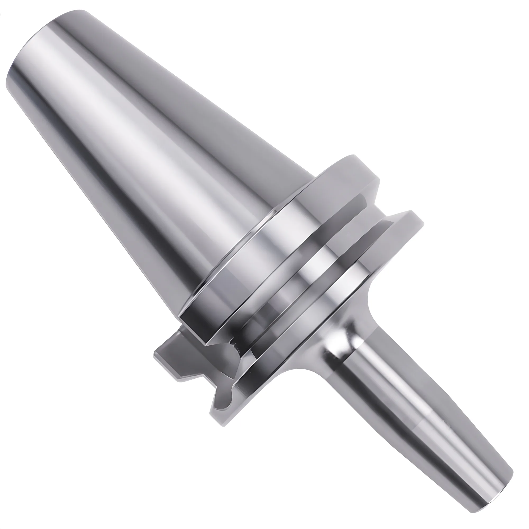
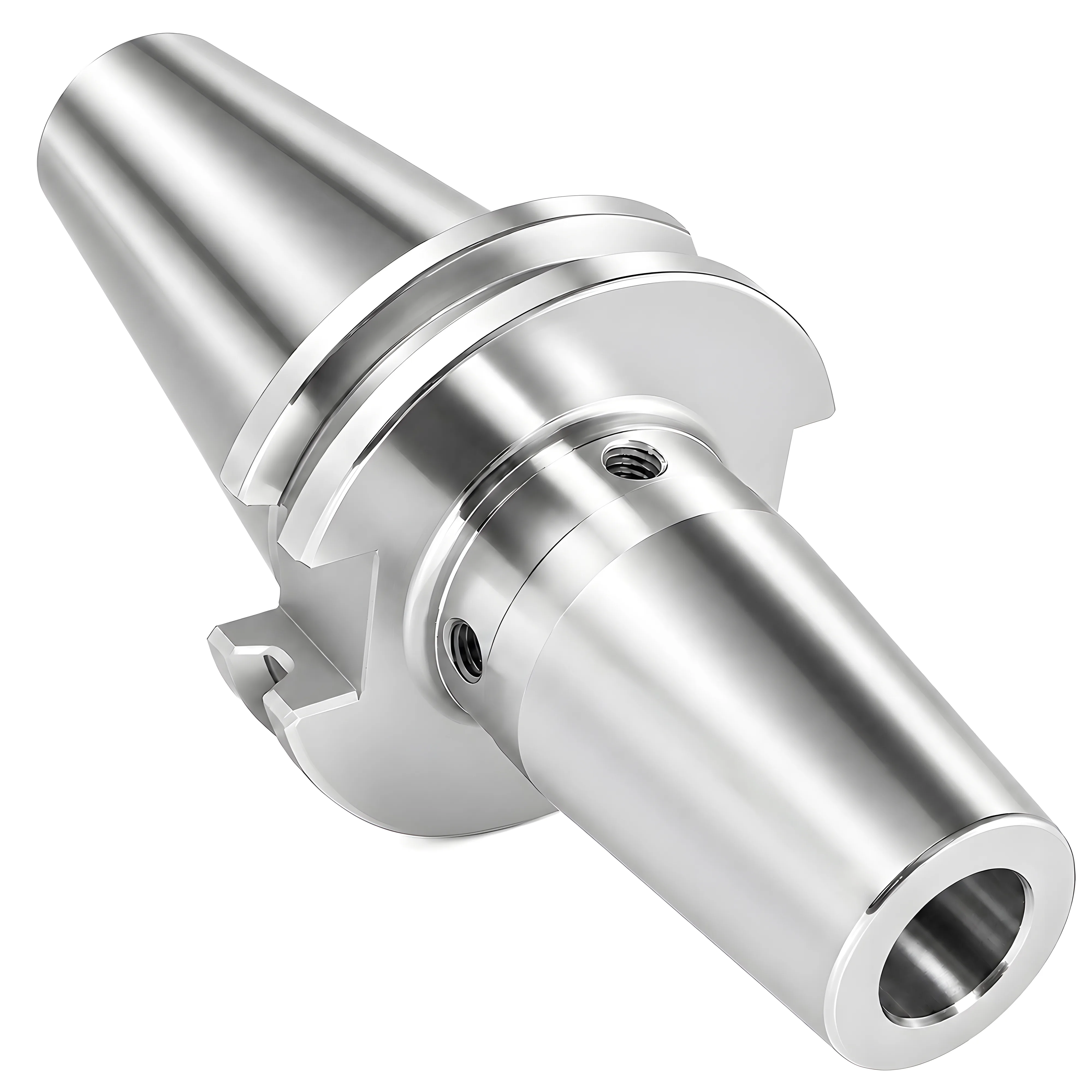
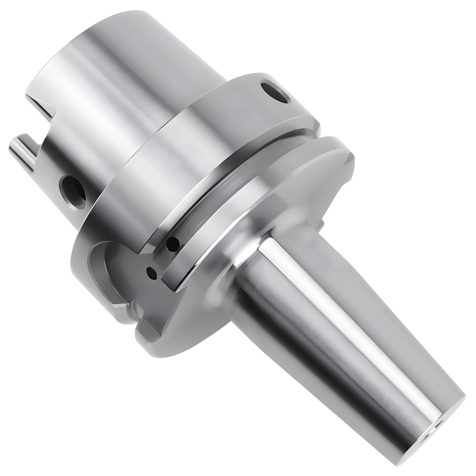
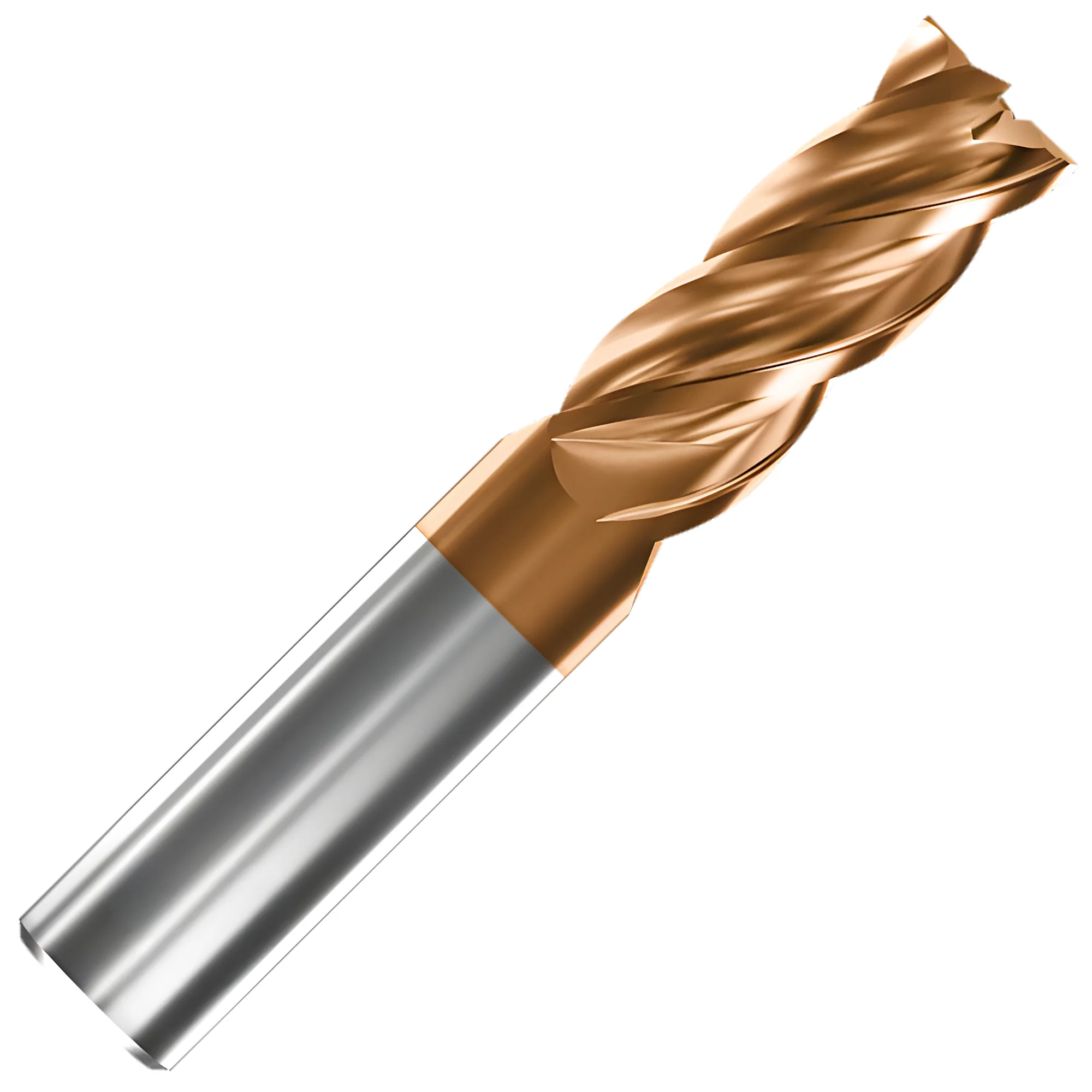
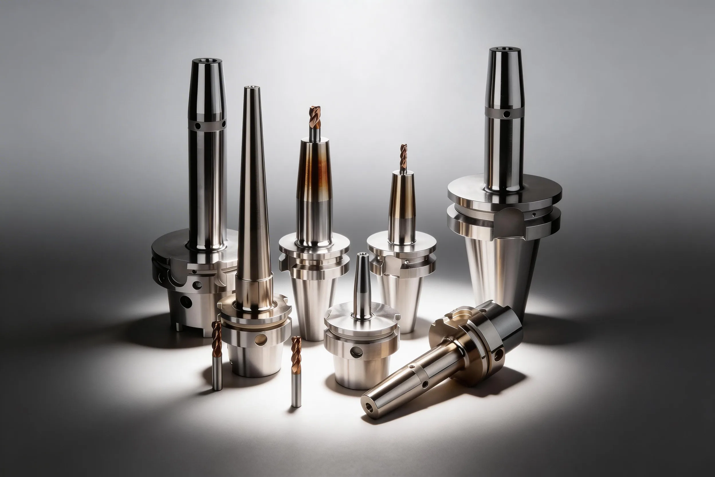
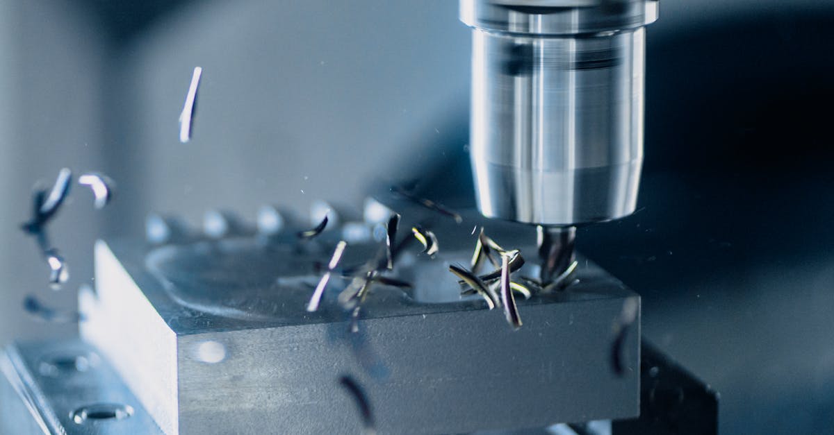
Shrink-fit holders achieve ≤0.003 mm TIR at 3×D and typically 25,000–40,000 N clamping force by heating the bore to 200–300°C for carbide shanks — enough to expand the bore by approximately 48–72 µm for a standard 20 mm holder (per ΔD ≈ α × D × ΔT with α ≈ 12 × 10⁻⁶ /°C). At spindle speeds above 8,000 RPM, use G2.5-balanced assemblies; below 8,000 RPM, G6.3 is generally acceptable for standard shop work.
Quick Shrink-Fit Setup Reference
| Problem / Goal | Primary Action | Expected Impact |
|---|---|---|
| Tool won't release — bore too tight | Heat to 250–300°C and hold 5 s | Bore expansion of ~60–72 µm on 20 mm diameter; tool slides free |
| Poor surface finish after tool change | Verify bore temperature reached before insertion; check concentricity | Restores ≤0.003 mm TIR; Ra improves ~30–50% at high RPM |
| Vibration at >10,000 RPM after assembly | Balance assembled holder+tool to G2.5 on dedicated balancer | Reduces vibration amplitude ≥50% vs unbalanced assembly in typical setups |
| HSS tool will not release from the holder | Let the holder cool fully, confirm an h6 shank, then reheat once with the matched coil | Fast, localized heat opens the bore before the HSS shank — which expands almost as much as the holder — warms and grows with it |
| Premature holder bore wear | Confirm tool shank is h6 tolerance; avoid oversized shanks | Maintains interference fit over several thousand cycles (Kennametal rates up to 5,000 heat/shrink cycles) |
| Long wait before the holder can be handled | Use water-cooled contact cooling instead of blowing air | Approx. 20–30 s vs roughly 1.5–5 min with forced air, per manufacturer data |
Expected impact column reflects typical shop outcomes; actual results depend on holder design, induction coil match, and tool shank tolerance.
How Shrink-Fit Clamping Works
Shrink-fit holders clamp by interference fit — the bore is typically machined 0.008–0.015 mm smaller than the tool shank diameter at ambient temperature. This engineered undersize creates the clamping force: once the bore returns to room temperature after heating, it grips the shank with typically 25,000–40,000 N (per manufacturer specifications) — above even the top of the 3,000–25,000 N range typical of ER collets across ER11–ER40 sizes.
The physics follows the thick-walled cylinder expansion formula:
ΔD ≈ α × D × ΔT
Where ΔD is bore diameter expansion, α is the coefficient of thermal expansion (approximately 11–13 × 10⁻⁶ /°C for hardened tool steel), D is nominal bore diameter in mm, and ΔT is temperature rise in °C. For a 20 mm bore heated 250°C: ΔD ≈ 12 × 10⁻⁶ × 20 × 250 = 0.060 mm — meaning the bore grows roughly 60 µm, which is ample clearance to slide a standard h6 shank in cleanly. Temperature rise dominates this equation because it scales linearly, while bore size multiplies a fixed constant; doubling the bore diameter doubles the absolute expansion at the same temperature.
Runout of ≤0.003 mm TIR at 3×D is achievable with shrink-fit because there are no moving parts — no nuts, collets, or setscrews to introduce eccentricity. The bore concentricity is machined in once at the factory; each tool change simply resets to the same geometric center. This makes shrink-fit the preferred choice for tight-tolerance finishing, high-speed profiling, and long-overhang applications where ER or side-lock holders would allow too much deflection. For a comparison of shrink-fit against collet chuck and hydraulic chuck systems, see Collet Chuck vs Hydraulic Chuck.
Heating Temperature by Tool Shank Material
The correct heating temperature depends on the tool shank material, not just the holder size. Getting this wrong is the most common cause of damaged tooling and shortened holder bore life.
Carbide shanks (the most common in modern solid-carbide end mills) should be heated to 200–300°C. At this range, the holder bore expands by approximately 48–72 µm on a 20 mm shank — opening a clearance gap of ~40–60 µm above the design interference (which is 8–15 µm at room temperature) to allow easy tool insertion. Carbide — with its low thermal expansion coefficient (~5–6 × 10⁻⁶ /°C) — barely changes size, so the differential expansion is almost entirely in the holder steel.
HSS shanks can be shrink-fitted, and no manufacturer source we reviewed publishes a lower heating cap for them — the constraint is release, not shank hardness. HSS is tempered at roughly 550°C (552–566°C is a typical M2 range), far above the 200–300°C bore temperature, and in a correctly timed induction cycle of a few seconds the shank has little time to heat at all. The real difference is thermal expansion: HSS expands almost as much as the holder steel, so if heat soaks from the bore into the shank, the shank grows with the bore and the tool stays gripped. Machine makers list HSS shanks in h6 tolerance, often from Ø6 mm rather than Ø3 mm (BILZ and KELCH quote HSS Ø6–32 mm vs carbide Ø3–32 mm), and rely on fast, localized heating; if an HSS tool will not release, let the holder cool completely before a second attempt rather than heating longer.
Avoid exceeding 350°C: most tool holder steels are pre-hardened to 55–62 HRC, and sustained temperatures above this threshold begin to reduce that hardness. A holder that has been overheated will show reduced bore grip, increased runout after tool changes, and — in worst cases — visible discoloration (blue-purple oxidation typically indicates the ~280–350°C range; straw/yellow typically indicates ~220–270°C, though colors vary by steel alloy). Track each holder's thermal history if cycle counts are high.
Overheating Risks
Heating above 350°C risks permanent holder hardness loss — discard any holder showing blue or purple oxidation coloration. Straw-yellow coloration (typically ~220–270°C) is a borderline warning; track that holder closely for runout degradation. Use an induction unit with a calibrated temperature sensor rather than relying on color estimation alone, as color onset varies by steel alloy.
Induction Heating Equipment and Coil Selection
Induction shrink-fit units heat only the holder bore area — not the full holder body — by passing high-frequency alternating current through a coil matched to the holder diameter. The coil gap between coil inner diameter and holder outer diameter should be 1–3 mm for efficient energy transfer; too large a gap weakens magnetic coupling and requires longer heating times, increasing the risk of thermal spread.
Match the coil diameter to within ±2 mm of the holder body diameter for optimal heating. Many current units cover the whole Ø3–32 mm range with one coil adapted by stop discs or an adjustable coil (HAIMER: a single coil plus five stop discs); heavy-duty chucks up to Ø50 mm need a second, larger coil. Using a coil two sizes too large lengthens the heating time needed to reach bore temperature, during which conductive heat loss to the holder body becomes significant.
Dedicated shrink-fit machines covering the Ø3–32 mm range used by most BT30/BT40 (per JIS B6339) and HSK-A63 (per DIN 69893) holders are typically rated about 10–14 kW. Heating time is typically 2–8 seconds for a properly matched coil — short enough to minimize thermal spread but long enough for even bore expansion. Extra power mainly shortens each heat rather than widening the bore range: HAIMER rates its 10 kVA unit at approx. 8 s and its 13 kVA units at approx. 5 s on the same Ø3–32 mm range. Units with integrated pyrometers (non-contact IR temperature sensors) eliminate guesswork; set the target temperature and let the unit cut power automatically.
Cooling, not heating, sets the pace of a shrink-fit tool change: forced air takes roughly 1.5–5 minutes, while water-cooled contact cooling takes approx. 20–30 seconds. Lyndex-Nikken quotes 90–180 s for its air-cooling unit and BILZ approx. 300 s for its air-cooled Starter, while BILZ (20 s) and HAIMER (approx. 30 s) rate their water-cooled contact cooling bodies, which clamp around the heated zone. Faster cooling also reduces the chance of tool shifting while the interference fit re-forms; forced air is sufficient where only a few tools are changed per shift.
Balance Grade G2.5 vs G6.3: When It Matters
ISO 1940-1 defines balance quality grades (G grades) where G = e_per × Ω, with G in mm/s, e_per the permissible specific unbalance in µm (= g·mm/kg), and Ω the angular velocity in rad/s. A lower G number means tighter balance tolerance — a G2.5 assembly is permitted 2.5× less residual unbalance per unit mass than a G6.3 assembly at the same speed.
G6.3 is the general-purpose grade and is acceptable for spindle speeds below 8,000 RPM in most milling and turning applications. At 6,000 RPM (Ω = 628 rad/s), G6.3 permits approximately 10 µm of permissible specific unbalance (e_per = G/Ω = 6.3/628 ≈ 10 µm) — a value that generates centrifugal force well within the bearing preload of most standard spindles. Shops doing general steel milling, tapping, or low-speed finishing do not need to pay the premium for G2.5 certification.
G2.5 becomes necessary above 8,000 RPM, and is effectively required above 15,000 RPM for spindle bearing life. The centrifugal force from residual unbalance scales with RPM squared — doubling speed quadruples unbalance force. A G6.3 assembly that is acceptable at 6,000 RPM generates 2.8× higher centrifugal force at 10,000 RPM, which is enough to measurably reduce bearing life and cause surface finish degradation on thin-wall features. Above 25,000 RPM (common in HSK-A63 and HSK-E32 high-speed spindles), G1.0 or better is the appropriate target.
For a broader comparison of holder types and their speed-RPM compatibility, see Side Lock vs ER Collet vs Shrink-Fit End Mill Holders.
The key insight is that balance grade must be specified for the assembled tool+holder system, not the holder alone. A factory-balanced holder that leaves the supplier at G2.5 becomes effectively G6.3 or worse once a tool is inserted with different length or diameter than the reference arbor used for balancing. For critical high-speed work, always balance the complete assembly on a tool presetter or dedicated two-plane balancer after each new tool insert.
Two-plane balancing addresses dynamic (couple) unbalance that single-plane static balancing misses. A tool that is statically balanced — equal mass distribution around the rotation axis — can still have moment-type unbalance if the mass asymmetry varies along the tool length. Two-plane balancers measure at two axial planes, allowing independent correction weights to address both static and couple components. Above 15,000 RPM, two-plane balancing is the correct procedure for assembled tool holders.
Step-by-Step Safe Tool Change Procedure
Follow this sequence for every shrink-fit tool change to ensure consistent runout and operator safety.
Step 1 — Verify tool shank tolerance. Measure the shank diameter with a micrometer. It must be within the h6 tolerance band: for a 20 mm nominal, h6 = 20.000 to 19.987 mm (upper deviation 0, lower deviation –0.013 mm). An oversized shank above nominal diameter will jam the bore without heating; an undersized shank below h6 lower limit will not achieve the designed interference pressure.
Step 2 — Clean all surfaces. Wipe the tool shank and holder bore with a lint-free cloth and isopropyl alcohol. Any oil film, cutting fluid residue, or chip fragment in the bore will be clamped into position and will prevent bore-shank contact on that spot, creating an eccentric grip and increasing runout 2–5× above specification.
Step 3 — Heat the holder. Place the holder in the induction unit with a matched coil. Set target temperature (typically 250–280°C for a carbide-shank 20 mm holder). Heat for the manufacturer-recommended dwell time — typically 3–8 seconds at full power. Remove immediately when the target is reached.
Step 4 — Insert the tool with a depth-stop gauge. Use the depth-stop collar or gauge supplied with the shrink-fit station to position the tool at the correct axial depth before the bore begins to contract. The window for insertion is narrow: heat dissipates quickly, and a bore that starts contracting around a partially inserted tool cannot be adjusted without reheating. Set the depth stop before heating, insert in one smooth motion, and do not rotate the tool during insertion.
Step 5 — Cool to room temperature before measuring or using. Wait until the holder returns to ambient temperature (touch-cool on the outer body, or verify with an IR thermometer reading below 40°C). Measuring runout on a warm holder gives falsely low readings because the thermal gradient causes non-uniform bore geometry. In production environments, forced-air cooling takes roughly 1.5–5 minutes, while water-cooled contact cooling cuts the wait to approx. 20–30 seconds.
Step 6 — Verify runout. Mount the holder in the spindle and measure TIR with a dial indicator at 3×D from the holder nose. A correctly set-up shrink-fit holder typically measures ≤0.003 mm TIR — if the reading exceeds 0.005 mm, remove the tool, reheat, and check shank condition and cleanliness before reinserting.
Step 7 — Balance the assembly (above 8,000 RPM). For high-speed applications, balance the complete holder+tool assembly per Step 6. Insert correction weights in the holder's balance ring grooves, or use a dedicated dynamic balancer, targeting G2.5 or better.
Best Practice — Depth Stop is Non-Negotiable
Use the depth-stop gauge for every tool insertion — estimating depth by eye is unreliable and should be avoided. A tool inserted 1–2 mm too shallow shifts the center of mass rearward and changes the balance grade of the assembly by an unpredictable amount. In precision boring applications, axial position error of 1 mm corresponds directly to cutting depth error at the tip.
Common Mistakes and How to Avoid Them
Mistake 1: Re-using a holder that has been overheated. If a holder shows blue-purple oxidation coloring, it has been exposed to 280–350°C or above. The bore hardness has degraded and interference force is lower. Retire the holder; continued use leads to inconsistent runout that is difficult to diagnose because the geometry varies with each cycle. Blue-purple oxidation typically appears in the ~280–350°C range; straw-yellow coloration typically occurs in the ~220–270°C range — these are indicative, not precise, since coloration varies with steel alloy and oxidation time.
Mistake 2: Heating without a matched coil. An undersized coil heats only the near-bore area; an oversized coil heats the full shank uniformly with poor efficiency. Both produce inconsistent bore expansion. Match coil inner diameter to holder outer diameter within ±2 mm.
Mistake 3: Reheating a holder that has not cooled. If a tool will not release within the set heating time, do not heat it again straight away — HAIMER's operating manual warns that the chuck would be overheated and destroyed. Let the holder cool completely, check that the shank is h6 and undamaged and that the coil is set correctly, then make one new release attempt.
Mistake 4: Balancing the holder without the tool installed. Factory balance certificates apply to the holder with a reference arbor. A production tool of different mass, diameter, or length changes the assembly balance state. In shops running above 10,000 RPM, balance the complete assembly — holder plus the specific tool it will carry.
Mistake 5: Ignoring shank tolerance class. h6 is the correct tolerance for shrink-fit shanks. h8 or k6 shanks are occasionally encountered in older tooling; h8 is too loose (insufficient interference), and k6 shanks are oversized (will not release without extreme temperatures). Check shank tolerance before ordering new tooling for an existing shrink-fit holder series.
What temperature should I heat a shrink-fit holder to for a carbide shank?
For carbide shanks in typical 12–32 mm bore holders, heat to 230–280°C for a 3–8 second dwell. On a 20 mm bore this produces roughly 55–67 µm of bore expansion — enough clearance for standard h6 shanks. Avoid exceeding 300°C for routine changes; temperatures above 350°C risk permanent hardness loss in the holder bore.
When should I specify G2.5 vs G6.3 balance for a shrink-fit holder?
Use G6.3 for spindle speeds below 8,000 RPM, where residual unbalance force stays within normal spindle bearing capacity. Specify G2.5 for 8,000–25,000 RPM operations — centrifugal force scales with RPM squared, so a G6.3 assembly acceptable at 6,000 RPM generates roughly 6× more force at 15,000 RPM. Balance the complete assembled tool+holder system, not the holder alone.
How long does a shrink-fit holder bore last before it needs replacing?
Under clean conditions with h6 shanks and heating within 200–300°C, shrink-fit holders typically last several thousand heat cycles — Kennametal rates its holders (6 mm bores and up) for as many as 5,000 heat/shrink cycles with correct use. Bore diameter growth is the main wear mode; measure the bore annually or whenever runout consistently exceeds 0.005 mm TIR.
Can I use a shrink-fit holder with an HSS tool shank?
Yes — makers list HSS shanks in h6 tolerance, typically from Ø6 mm (BILZ, KELCH: HSS Ø6–32 mm vs carbide Ø3–32 mm). A 200–300°C bore does not soften HSS, which is tempered at roughly 550°C; the issue is release, as HSS expands almost as much as holder steel. Heat fast, and let a stuck holder cool before reheating.
Why does my shrink-fit holder show higher runout after reassembly than it did initially?
The most common cause is a dirty bore or shank — any particle clamped at the interface creates eccentricity. Secondary causes include bore diameter growth from overheating cycles (measure bore directly), or a tool shank outside the h6 tolerance band. Clean and measure both surfaces; if bore diameter has grown beyond h6 interference range, retire the holder.
Clean surfaces, matched coil, correct temperature, G2.5 above 8,000 RPM.
Shrink-fit holders deliver ≤0.003 mm TIR and typically 25,000–40,000 N clamping force — but only when the setup procedure is followed precisely. Heat carbide shanks to 230–280°C with a matched coil, insert with a depth-stop gauge, cool fully before measuring, and balance the complete assembly to G2.5 for any spindle speed above 8,000 RPM. The most common quality loss comes from dirty interfaces, overheating (oxidation coloring is the indicator), and balancing the holder alone rather than the assembled tool+holder system.
Sources
- ISO 1940-1:2003 — Mechanical Vibration: Balance Quality Requirements for Rotors
- BIG DAISHOWA Shrink-Fit Tool Holders — Clamping Force and Runout Data
- Schunk TENDO Shrink-Fit System — Technical Documentation
- Haimer Power Shrink Chuck — Balance and Speed Specifications
- Kennametal — Technical Information: Shrink Fit (heat/shrink cycle rating, HSS and carbide shanks)
- HAIMER — Power Clamp Operating Manual 917000-0020_EN (heating times, reheating warning)
- BILZ — ThermoGrip Shrink Units (clamping ranges, cooling times)
- Lyndex-Nikken — Shrink Fit Catalogue (14 kW unit, 2–7 s heating, 90–180 s air cooling)
- Hudson Tool Steel — M2 High Speed Steel Technical Data (tempering range)