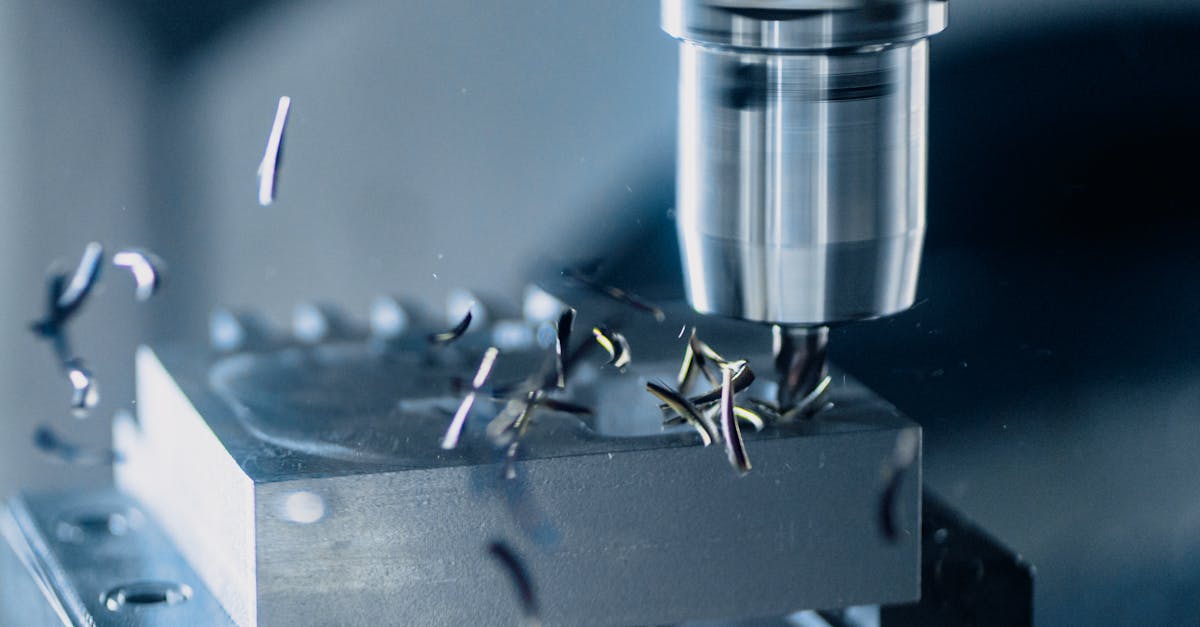
CNC tool holding spans three taper systems (BT at ~20 N/µm, CAT at ~20 N/µm, HSK at ~50 N/µm stiffness) and four clamping technologies — ER collets (≈0.005 mm UP/AA to ≤0.020 mm Class 2 TIR, ~3,000-25,000 N depending on size, typical estimates), hydraulic chucks (0.003 mm TIR, 10,000-20,000 N), shrink-fit holders (0.003 mm TIR, 8,000-40,000 N depending on bore), and drill chucks. Each combination of taper and clamping type suits different speed ranges, cutting forces, and precision requirements.
Every CNC setup involves a chain of components: spindle, taper interface, tool holder body, clamping mechanism, and finally the cutting tool. Weakness at any point in this chain degrades the entire system. A premium carbide end mill in a worn collet will underperform a mid-grade tool in a properly matched holder. This guide covers every layer of that chain -- from spindle taper standards through clamping technologies to maintenance best practices -- so you can make informed decisions for your shop.
Tool Holder Taper Systems
The taper is the interface between the tool holder and the machine spindle. HSK-A63 (DIN 69893) delivers approximately 50 N/µm radial stiffness — about 2-3x higher than equivalent BT40 or CAT40 (~20 N/µm) — under standard manufacturer test conditions, because the dual face-and-taper contact resists radial deflection that taper-only systems do not.
| Parameter | BT | CAT | HSK-A | HSK-E/F |
|---|---|---|---|---|
| Standard | JIS B6339 / MAS 403 | ANSI/ASME B5.50 | DIN 69893 | DIN 69893 |
| Taper Ratio | 7:24 | 7:24 | 1:10 (hollow) | 1:10 (hollow) |
| Contact Type | Taper only | Taper only | Face + taper | Face + taper |
| Radial Stiffness (typical) | ~20 N/µm (BT40) | ~20 N/µm (CAT40) | ~50 N/µm (HSK-A63) | ~50 N/µm |
| Typical Max Speed | 12,000-15,000 RPM | 10,000-15,000 RPM | 15,000-25,000 RPM | 30,000-40,000+ RPM |
| Drive Slots | Yes | Yes | Yes | None |
| Tool Change Speed | Standard | Standard | Fast | Fast |
| Primary Region | Asia | North America | Global (growing) | Global (specialty) |
Stiffness values measured under specific gauge length and test conditions; vary by setup. Data sourced from BIG DAISHOWA, Haimer, and Sandvik comparative literature.
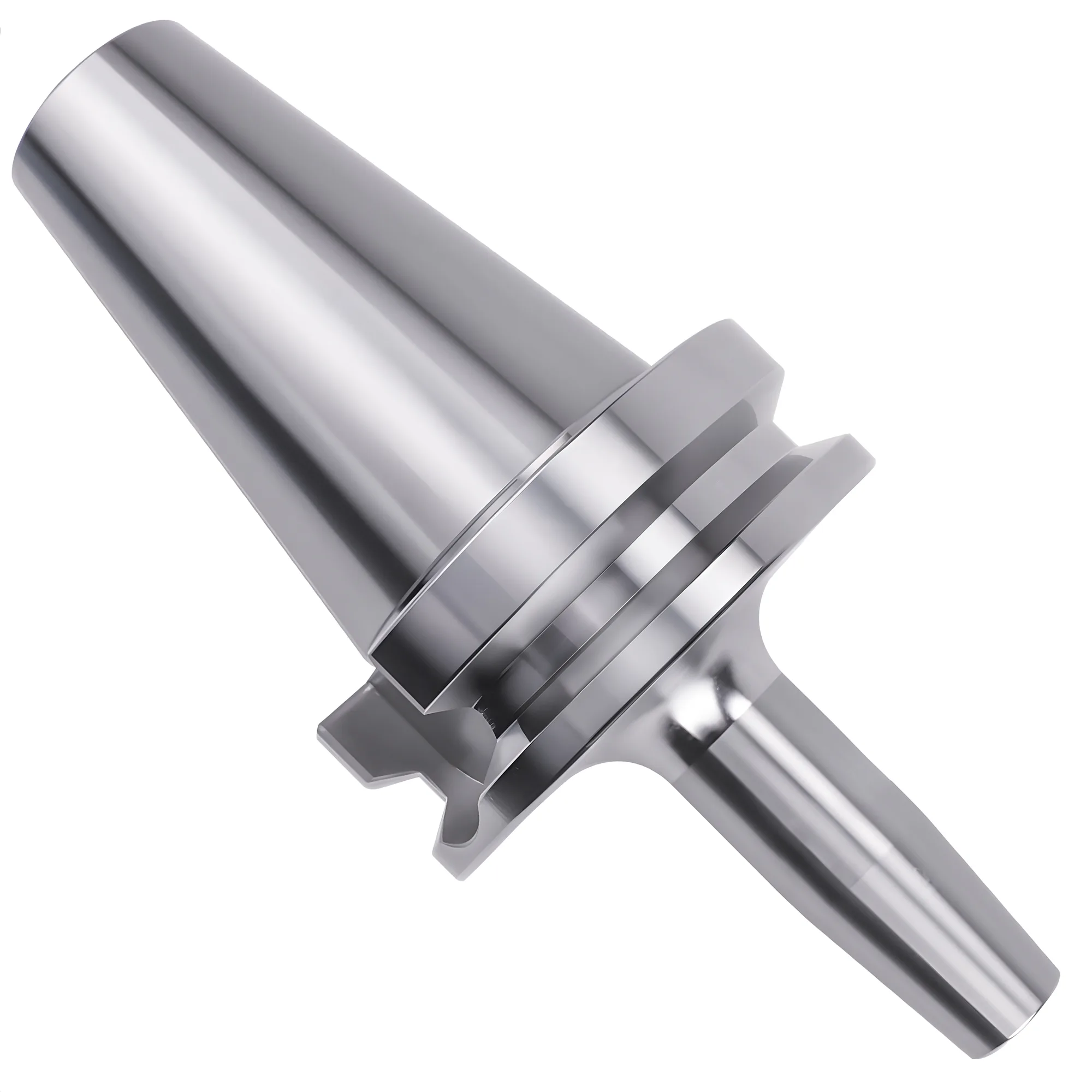
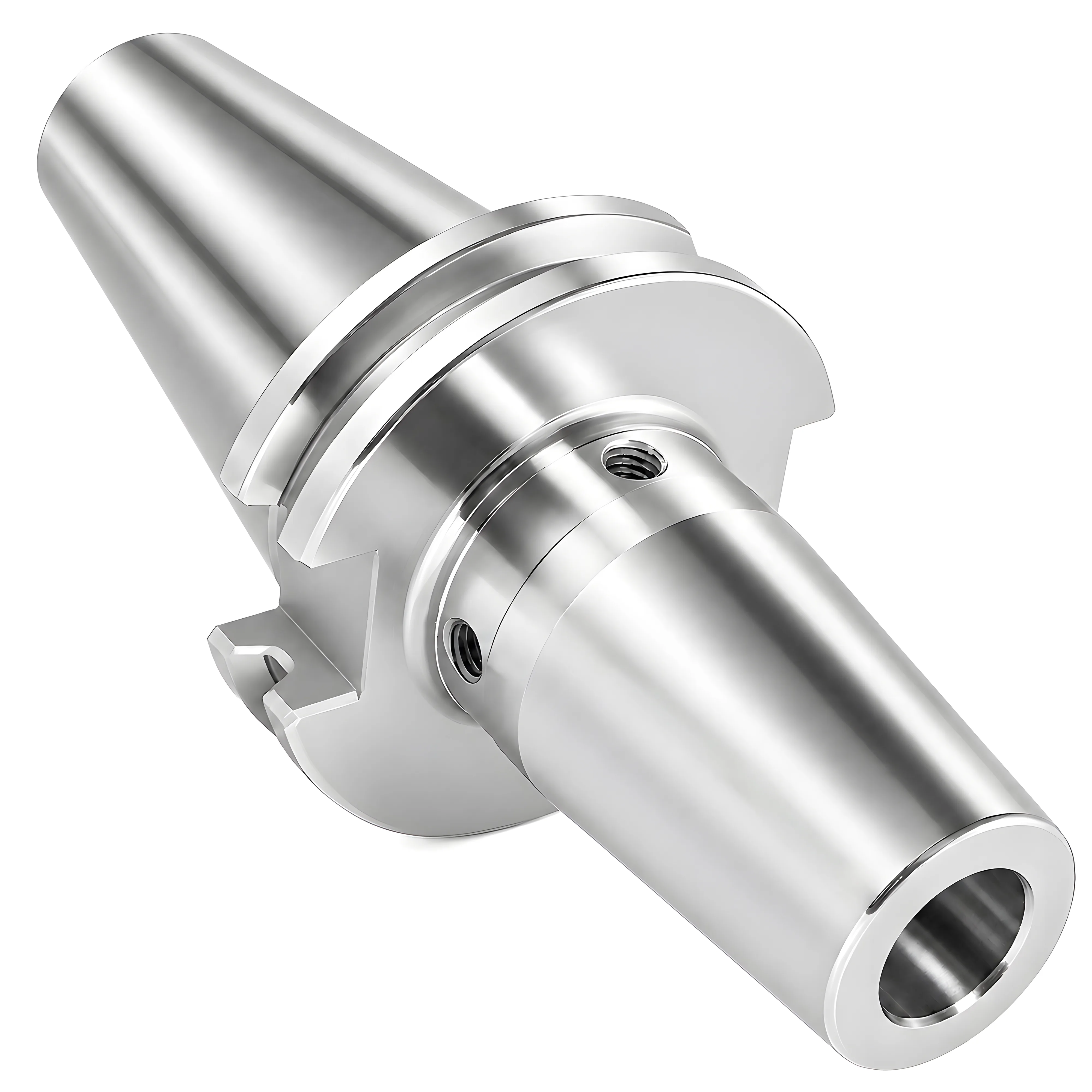
BT and CAT share the same 7:24 taper geometry but are not interchangeable -- the V-flange dimensions and pull stud threads differ between the two standards. Both rely on taper-only contact, which means the holder can shift axially at high speeds as centrifugal force expands the spindle bore. This typically limits standard practical operating speeds to approximately 12,000-15,000 RPM. Dual-contact variants (Big Plus for BT, Big Plus/Dual Contact for CAT) add face contact to extend the usable range to about 20,000 RPM. Premium-balanced (G2.5) BT/CAT holders such as hydraulic or shrink-fit versions are rated by manufacturers like SYIC and Harlingen up to 25,000 RPM. MAS 403 is the Japanese auxiliary standard for the BT pull stud (retention knob), which is why BT holder catalogs cite it alongside JIS B6339 when matching a holder and pull stud to a spindle.
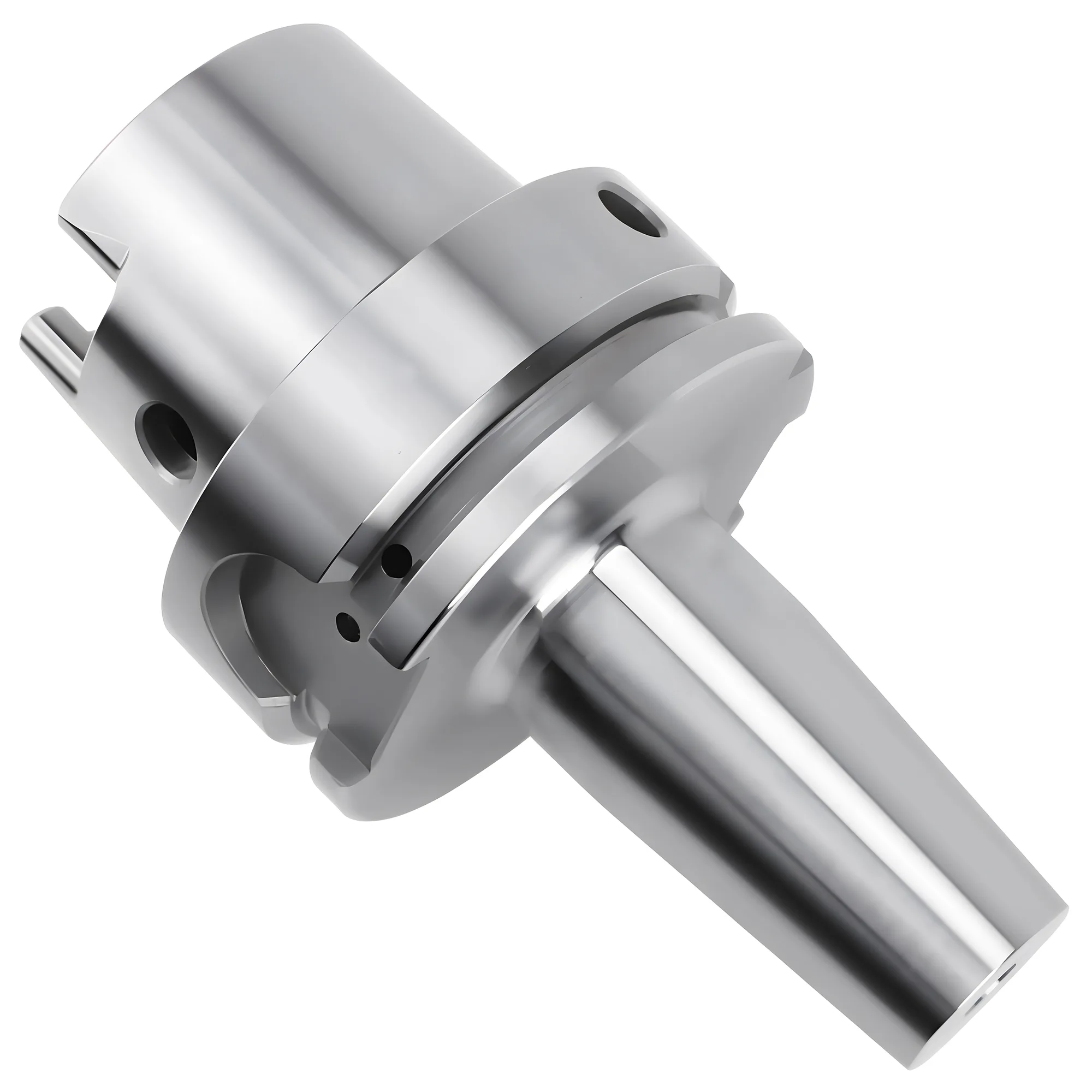
HSK eliminates these limitations with a hollow 1:10 taper that clamps from inside, pulling the flange into simultaneous face contact. This dual-contact design provides 2-3 times the radial stiffness of equivalent BT/CAT sizes and maintains rigidity at high speeds — but the specific speed depends on the HSK form. HSK-A and HSK-B have rear drive slots in the flange (asymmetric), limiting balance grade and practical speed to about 15,000-25,000 RPM in production. HSK-E and HSK-F eliminate drive slots entirely for fully symmetric design, enabling G1.0 balance and operation at 30,000-40,000+ RPM in high-speed aluminum and finishing applications. ISO 12164 is the international counterpart of DIN 69893 and defines the same hollow-taper interface dimensions, so HSK holders are specified to either.
Interchangeability
BT and CAT holders look similar but are NOT interchangeable. The pull stud threads (BT uses JIS standard, CAT uses ANSI standard) and flange keyway positions differ. Installing the wrong holder can damage the spindle.
For a detailed comparison of these three systems, including speed range charts and application recommendations, see the full BT vs CAT vs HSK comparison guide.
Collet Systems: ER, 5C, and R8
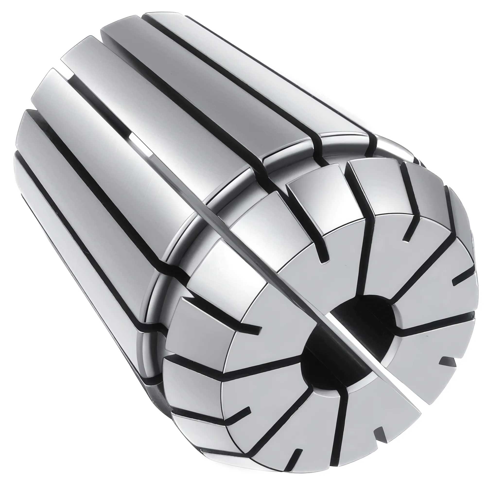
Collet systems use a tapered, slotted sleeve that contracts radially under clamping force to grip the tool shank. ER collets per DIN 6499 / ISO 15488 hold Class 2 runout to ≤0.020 mm TIR (10-26 mm shank, tested at the standard's specified projection), while precision UP/AA grades reach ≈0.005 mm — provided the spindle, holder, collet, and h6 shank all meet matching tolerances.
ER Collets (DIN 6499 / ISO 15488)
ER collets are the dominant standard for CNC milling. The number after "ER" indicates the collet outer diameter in millimeters. Each collet clamps a 1 mm band on ER16–ER40 and a 0.5 mm band on ER11; many makers also sell metric sizes in 0.5 mm steps, so the size chart, not the label, tells you what fits. Matching collet size and grade to the job is covered in the ER collet selection guide.
| ER Size | Clamping Range | Nut Tightening Torque (standard / mini nut) | Typical Application |
|---|---|---|---|
| ER11 | 1-7mm | 24 Nm / 16 Nm | Micro-machining, engraving |
| ER16 | 1-10mm | 56 Nm / 24 Nm | Light milling, drilling |
| ER20 | 1-13mm | 80 Nm / 28 Nm | General purpose |
| ER25 | 1-16mm | 104 Nm / 32 Nm | Standard milling |
| ER32 | 2-20mm | 136 Nm / — (about 100 ft-lb) | Heavy milling (most common) |
| ER40 | 3-26mm | 176 Nm / — (about 130 ft-lb) | Heavy-duty applications |
Clamping ranges are the ISO 15488 range across Forms A and B. ISO 15488 standardizes ER11–ER40; ER8 and ER50 are widely made manufacturer extensions below and above that range. Torque values are the REGO-FIX recommended tightening torque for the largest collet bore of each size; ISO 15488 sets no nut torque, smaller bores take less (for example 8 Nm for ER11 collets below 3 mm), mini nuts exist only up to ER25, and other nut makers publish different figures — when the nut brand is known, use the value on its data sheet.
5C Collets
5C collets are primarily used in lathes, indexing fixtures, and grinding applications. They hold up to 1-1/16 in (about 27 mm) and close through a draw bar or collet closer. Their key advantage is high accuracy (under 0.005mm TIR) with a draw-in closer design (precision grades). However, each 5C collet accepts only one specific diameter or a very narrow range, making them less flexible than ER systems.
R8 Collets
R8 collets are the standard for Bridgeport-style manual milling machines. They feature a 7/16-20 draw bar thread and are limited to approximately 3,000 RPM. R8 collets are not suitable for CNC applications due to their speed limitations and lower accuracy compared to ER systems.
✦ ER Collets Best For
- CNC milling -- widest flexibility
- Job shops with varied tool sizes
- Fast tool changes (15-30 seconds)
- Available in standard and precision grades
✦ 5C Collets Best For
- Lathe work and second operations
- Grinding and inspection fixtures
- Indexing applications
- Maximum accuracy on single diameters
Hydraulic Chucks vs Collet Chucks
The choice between hydraulic and collet chucks is one of the most impactful tool holding decisions for CNC milling operations. Hydraulic chucks typically hold runout to ≤0.003 mm TIR at 3xD projection, compared to 0.005 mm (UP/AA) to 0.020 mm (Class 2, normal grade) for ER collets, with damping that can reduce surface roughness by 0.2-0.4 Ra in chatter-prone finishing of 4140 steel.
Collet chucks grip the tool through mechanical deformation of a slotted collet. The segmented design provides good clamping force across a range of diameters but introduces small asymmetries that limit achievable runout.
Hydraulic chucks use pressurized oil in a sealed chamber to expand a thin-wall sleeve uniformly around the tool shank. The continuous 360-degree contact and oil damping produce measurably better runout and surface finish.
| Factor | Collet Chuck (ER32) | Hydraulic Chuck |
|---|---|---|
| Runout (TIR) | 0.005-0.020mm | 0.003mm or less |
| Clamping Force | 10,000-15,000 N (typical estimate) | 10,000-20,000 N |
| Damping | Low | High (3-5x mechanical) |
| Tool Change Time | 15-30 sec | 20-40 sec |
| Diameter Flexibility | 1mm range per collet | Fixed bore (h6 shank) |
| Cost per Unit | $80-$200 (chuck + collet) | $300-$600 |
| Consumable Cost | $8-$25 per collet | None (seal service at 10,000+ cycles) |
Decision Shortcut
If you are struggling to achieve target surface finish with ER collets — particularly at stickout exceeding 4xD or in harder materials — a hydraulic chuck's damping can improve finish by 0.2-0.4 Ra in chatter-prone conditions. For general machining with short stickout and no chatter, ER collets offer better value through flexibility.
The damping characteristics of hydraulic chucks deserve special attention. The oil chamber absorbs high-frequency vibrations (chatter) that transfer between tool and spindle. In finishing operations where chatter is present or borderline, this can translate to 0.2-0.4 Ra improvement. On rigid setups with short projection, the difference may be negligible.
For the full head-to-head analysis, see the Collet Chuck vs Hydraulic Chuck comparison.
Drill Chucks for CNC Applications
Drill chucks hold straight-shank drills, taps, and reamers using three self-centering jaws. Drill chucks typically hold 0.05-0.30 mm TIR at the chuck nose (0.05-0.08 mm for integrated CNC drill chuck holders, 0.08-0.15 mm keyless, 0.10-0.30 mm keyed); for hole-making where runout must stay below 0.02 mm, ER collets gripping straight-shank drills are preferred over arbor-mounted drill chucks.
Keyed drill chucks use a gear-driven mechanism tightened with a chuck key, providing maximum grip strength and repeatable clamping torque. They are preferred for heavy-duty drilling in steel, large diameter bits (above 13mm), and tapping operations where tool slip is unacceptable.
Keyless drill chucks feature a self-locking mechanism tightened by hand, enabling one-handed tool changes without a key. Modern keyless designs incorporate ratcheting mechanisms that grip tighter under cutting load, though they still cannot match the absolute grip strength of keyed designs.
For CNC machining centers, drill chucks mount via arbor adapters to BT, CAT, or HSK tapers. The additional interface (arbor + chuck) increases stack-up runout. For precision hole-making where runout must stay below 0.02mm, ER collets holding straight-shank drills are generally preferred over drill chucks.
For detailed selection criteria including capacity options and mounting configurations, see the Drill Chuck Selection Guide.
Shrink-Fit and Press-Fit Holders
Shrink-fit holders represent the highest-performance clamping technology available for CNC milling. Shrink-fit holders generate 8,000-40,000 N of clamping force (depending on bore diameter) through thermal interference fit alone, with continuous metal-to-metal contact that maintains ≤0.003 mm runout at 3xD without seals, slots, or moving parts.
The holder bore is typically manufactured 0.01-0.02mm smaller than the tool shank diameter. An induction heater expands the bore in 3-8 seconds, allowing the tool to be inserted. As the holder cools (30-120 seconds), the bore contracts and grips the shank with direct metal-to-metal contact along the entire length.
The advantages of shrink-fit holders are significant:
- Maximum rigidity -- continuous metal-to-metal contact with no gaps, slots, or fluid layers
- Best balance -- symmetrical geometry with no moving parts, seals, or asymmetric features
- Minimal overhang -- slim nose profile allows access to tight pockets and deep cavities
- Zero maintenance -- no collets to wear, no seals to replace, no oil to degrade
The trade-offs are equally clear:
- Tool change time -- a full heat-insert-cool cycle takes 2-3 minutes versus 15 seconds for an ER collet change
- Single diameter -- each holder accepts exactly one shank size (no flexibility)
- Equipment cost -- requires an induction heating unit ($2,000-$8,000)
- Bore wear -- repeated heating cycles gradually enlarge the bore; annual bore measurement is required
Heat Source Selection
Use induction heating for shrink-fit operations. Flame heating creates uneven thermal expansion that can warp the holder and alter its metallurgical properties. Oven heating works but is too slow for production use.
Press-fit (force-fit) holders operate on a similar interference principle but use hydraulic or mechanical force to insert the tool at room temperature. They are less common than shrink-fit in CNC milling but appear in dedicated production tooling where absolute rigidity is required and tools are rarely changed.
Runout, Balance, and Maintenance
Runout
Runout is the deviation of the tool's actual rotation axis from the spindle's true rotation axis. BIG DAISHOWA's one-tenth rule — derived from finishing tests in steel — estimates approximately 10% tool life loss per 2.5 µm (0.0001") of runout, because asymmetric chip load concentrates wear on the loaded edge while the opposite edge barely engages.
| Holder Type | Typical Runout at 3xD | Best Achievable |
|---|---|---|
| ER Collet (standard) | 0.010-0.015mm | 0.008mm |
| ER Collet (AA grade) | ≤0.005mm | 0.003mm |
| Hydraulic Chuck | 0.003mm | 0.002mm |
| Shrink-Fit | 0.003mm | 0.002mm |
| Drill chuck (keyless / integrated) | 0.05-0.15mm | 0.05mm |
The actual impact of the one-tenth rule varies with material, engagement, and flute count. The effective chip load on the cutting edge closest to the workpiece increases by the runout value, while the opposite edge barely cuts. This asymmetric loading causes uneven wear, premature failure, and degraded surface finish.
Balance
At high spindle speeds, any mass asymmetry in the tool holder assembly creates centrifugal force that increases effective runout and accelerates spindle bearing wear. Balance quality is measured per ISO 1940 using G-grades.
ISO 1940-1:2003 defines the G-grade methodology and the formula for permissible residual unbalance, but the specific RPM thresholds for tool holder applications come from manufacturer practice — not the standard text. The standard provides the framework; manufacturers apply it to their products.
Shrink-fit holders inherently provide the best balance due to their simple, symmetrical geometry. ER collet chucks require precision-balanced variants (with balanced nuts and optimized mass distribution) for high-speed applications. Hydraulic chucks typically achieve G2.5 without additional balancing.
Maintenance Schedule
| Component | Inspection Frequency | Method | Replace When |
|---|---|---|---|
| ER collets | Weekly | Dial indicator on test bar | Runout exceeds spec by 0.005mm |
| ER collet taper | Monthly | Visual + dimensional check | Visible wear marks or galling |
| Hydraulic seals | Quarterly | Leak check under pressure | Requires >1/4 turn extra to clamp |
| Shrink-fit bore | Annually | Bore gauge measurement | Oversized by >0.005mm |
| Clamping nut threads | Monthly | Visual inspection | Cross-threading or burrs |
Extending Collet Life
Never exceed the manufacturer's specified clamping torque. Over-torquing causes plastic deformation of the collet slots, permanently reducing both clamping force and concentricity. Use a calibrated torque wrench for every collet change.
Selection Framework
Choosing the right tool holding system requires matching holder characteristics to your dominant machining application. The dominant operation type — roughing, finishing, or mixed — drives holder selection more than the cutting tool itself, because clamping force, runout, and damping characteristics determine whether a holder protects or wastes the tool's capability.
Step 1: Identify your spindle interface. Your machine's taper (BT, CAT, HSK) determines the available holder options. If purchasing a new machine, select the taper based on your speed requirements: BT/CAT for under 15,000 RPM general work, HSK for high-speed or high-precision applications.
Step 2: Determine your primary operation type.
- Roughing (high material removal): Prioritize clamping force and pullout resistance. ER collet chucks or side-lock holders with Weldon-flat tools.
- Finishing (tight surface specs): Prioritize low runout and vibration damping. Hydraulic chucks for surface finish below Ra 1.6; shrink-fit for high-speed finishing above 15,000 RPM.
- General purpose (mixed operations): ER collet chucks provide the best balance of flexibility, performance, and cost.
- Drilling and hole-making: ER collets for precision holes; drill chucks for standard drilling.
Step 3: Evaluate economics.
| Scenario | Recommended System | Rationale |
|---|---|---|
| Job shop, varied work | ER collet chucks | One chuck covers many diameters; lowest cost per tool change |
| Production line, fixed tools | Hydraulic or shrink-fit | Consistent runout justifies higher per-holder cost |
| High-speed aluminum (20,000+ RPM) | Shrink-fit in HSK | Best balance and rigidity at speed |
| Finishing station | Hydraulic | Damping improves surface finish measurably |
| Mixed roughing and finishing | ER rough + hydraulic finish | Strategic deployment minimizes cost while maximizing quality |
For a cost-benefit analysis of when to upgrade holders, see the Tool Holding ROI guide. For vises, lathe chucks, and live centers (workpiece holding rather than tool holding), see the workholding selection guide.
Quick Tool Holder Selection by Application
| Scenario | System Type | Runout (TIR) | Speed Limit | Why |
|---|---|---|---|---|
| General CNC milling, mixed tool sizes | ER collet chuck (DIN 6499) | 0.005-0.020 mm | 20,000-25,000 RPM (G2.5) | One chuck covers a 1 mm diameter band per collet; lowest cost per tool change |
| Finishing 4140/stainless, surface finish ≤ Ra 1.6 | Hydraulic chuck | ≤0.003 mm | 25,000 RPM | Oil damping (3-5x mechanical) suppresses chatter and tightens runout below ER collet floor |
| High-speed aluminum / hardened steel finishing | Shrink-fit holder | ≤0.003 mm | 25,000-40,000 RPM | Symmetric monolithic geometry holds G2.5/G1.0 balance at speeds where ER nuts unbalance |
| Roughing with high pull-out risk (Weldon shanks) | Side-lock holder | 0.010-0.020 mm | 12,000 RPM | Set screw on flat resists axial pull-out under heavy radial load; runout secondary |
| 30,000-40,000+ RPM micro/finishing | HSK-E or HSK-F shrink-fit | ≤0.003 mm | 30,000-40,000+ RPM | No drive slots → fully symmetric → G1.0 balance achievable; dual face/taper contact maintains rigidity |
| Drilling above 13 mm in steel, no slip allowed | Keyed drill chuck | 0.10-0.15 mm | 3,000 RPM | Gear-driven mechanism delivers maximum and repeatable grip torque; runout adequate for hole-making |
| Job shop, varied work, single machine | ER32 chuck on BT40/CAT40 | 0.005-0.020 mm | 15,000 RPM | Best flexibility-per-dollar; 2-20 mm clamping range covers most milling tools |
Match the holder to the operation, not the other way around.
Most productive CNC shops use multiple tool holding technologies strategically: ER collet chucks for general work and roughing where flexibility matters, hydraulic chucks on finishing stations where runout and damping improve part quality, and shrink-fit holders for high-speed production where rigidity and balance are critical. No single holder type is optimal for all applications. Select your spindle taper first (BT/CAT under 15,000 RPM, HSK above), then choose clamping technology based on your dominant operation type.
What is the most important specification when choosing a tool holder?
Runout at the tool tip is the most critical specification. Per BIG DAISHOWA's one-tenth rule, each 2.5 µm of runout costs approximately 10% of tool life. For finishing operations, target holders with runout below 0.005mm at 3xD projection length.
Can I use BT tool holders in a CAT spindle?
No. BT and CAT holders share the same 7:24 taper angle but use different pull stud threads (JIS for BT, ANSI for CAT) and different flange keyway positions. Forcing the wrong holder risks spindle damage and an unsafe retention state. Always confirm holder compatibility against your machine's spindle standard before installation.
When should I upgrade from ER collet chucks to hydraulic chucks?
Upgrade when your finishing operations consistently require surface finish below Ra 1.6, when tool life on expensive carbide end mills is a significant cost factor, or when you are machining at long stickout ratios (above 4xD) where chatter control matters.
How often should I replace ER collets?
Standard ER collets last 500-1,000 clamping cycles with typical use, or 1,500-3,000 with consistent torque wrench practice and h6-tolerance shanks. Check runout with a dial indicator weekly and replace any collet that exceeds the manufacturer's runout specification by more than 0.005mm.
Is shrink-fit worth the investment for a job shop?
Generally no. Shrink-fit excels in production environments with dedicated tooling and high spindle speeds. The 2-3 minute tool change cycle and single-diameter limitation make it impractical for job shops with frequent setups. ER collet chucks remain the best general-purpose choice for varied work.
Sources
- ISO 15488:2003 — Collets with 8° setting angle for tool shanks
- DIN 69893: Hollow Taper Shank (HSK) Tool Holders
- ISO 12164: Hollow Taper Interface with Flange Contact Surface
- Machinery's Handbook: Tool Holding and Workholding Systems
- REGO-FIX — Recommended tightening torque for ER and MR clamping nuts