Effective 5-axis workholding eliminates 60–80% of setup time by enabling complete part machining in a single clamping — but only when zero-point systems, clamp geometry, and part orientation are engineered together. A misplaced clamp that blocks spindle access forces a second setup, negating the primary advantage of 5-axis machines. This guide covers zero-point clamping selection, single-setup part design rules, and the interference clearance calculations that determine whether your fixture can actually reach every feature.
Quick 5-Axis Workholding Reference
| Problem / Goal | Primary Action | Expected Impact |
|---|---|---|
| Multiple setups required for one part | Redesign fixture for ≥270° rotational clearance | Reduce setups from 3–4 to 1, saving 30–90 min/part |
| Clamp collision with spindle nose | Apply 30 mm minimum radial clearance rule from clamp top | Eliminate collision with 5-axis head at full tilt |
| Repositioning error accumulates | Switch to zero-point system (≤0.005 mm repeat accuracy) | Hold feature-to-feature tolerance ≤0.01 mm across setups |
| Workpiece vibration in long-reach cuts | Add low-profile support below part, not beside it | Reduce chatter by 40–60% without blocking spindle access |
| Fixture setup time too long | Standardize to 52 mm or 96 mm zero-point grid | Cut fixture changeover from 20–30 min to under 3 min |
| Thin-wall distortion from clamping | Use vacuum or wrap-around soft jaws | Reduce workpiece deformation from 0.05 mm to ≤0.01 mm |
Why 5-Axis Workholding Differs From 3-Axis
5-axis machining requires workholding that provides access from at least five directions simultaneously, not just top and side. In 3-axis work, a vise or strap clamp only needs to avoid the tool path in the vertical Z axis. In 5-axis simultaneous cutting, the spindle tilts up to ±90° (trunnion) or ±120° (swivel head), meaning any mass rising more than a few centimeters above the table creates a collision risk with the rotating head assembly.
The economics reinforce this constraint. A typical complex aerospace bracket requires 4–6 setups on a 3-axis machine — each setup consuming 20–45 minutes of alignment time and introducing datum shift errors of 0.02–0.05 mm per reset. A single 5-axis setup eliminates that cascade, but only if the workholding geometry allows the spindle to reach all features without repositioning. The break-even point is clear: if your workholding forces more than one setup, you lose the primary advantage of 5-axis investment.
Zero-point clamping systems address the repeat-accuracy problem when multiple setups are genuinely unavoidable. Systems conforming to the 52 mm grid standard (widely adopted by Schunk, Renishaw, and Erowa) deliver ≤0.005 mm repeat positioning accuracy — compared to ≤0.02 mm for a conventionally indicated vise setup. That 4× accuracy improvement is what allows 5-axis machines to hold ±0.01 mm feature-to-feature tolerances across setups. For a broader comparison of vise types and jaw selection for 5-axis setups, see our workholding selection guide.
Zero-Point Clamping Systems: Selection and Setup
Zero-point clamping systems use precision-ground shanks (nipples) that lock into pneumatically or hydraulically actuated drawbar mechanisms in a sub-plate. The primary selection criteria are grid pitch, pull-down force, and shank diameter — not brand.
Grid Pitch Options
The two dominant grid standards are 52 mm and 96 mm pitch. The 52 mm grid supports workpieces up to approximately 200 × 200 mm and fits trunnion-style 5-axis tables directly. The 96 mm grid handles larger pallets (400 × 400 mm and above) suited to horizontal 5-axis machining centers and pallet-changing cells. Mixing grid sizes within a production line forces adapter plates that add 30–50 mm of height — height that directly reduces spindle clearance.
Pull-Down Force and Clamping Security
The pull-down force specification (15,000–25,000 N per module) describes the axial retaining force with pneumatics de-energized — the "spring-locked" default state. During machining, the workpiece is held mechanically with no pneumatic or hydraulic pressure required. This is a critical safety distinction: if air supply fails mid-cycle, a zero-point system retains the part. A conventional pneumatic vise may release.
For Ti-6Al-4V and Inconel 718 operations, use a minimum of four zero-point modules per fixture to distribute the cutting force reaction across multiple retention points. Milling titanium at 60–80 m/min generates tangential cutting forces of 1,500–3,000 N for a 16 mm diameter end mill at 1.5 mm axial depth — forces that must be reacted through the pallet, not just the clamping shank friction interface.
Best Practice: Test Retention Force Before Cutting
Before first article runs on any new 5-axis fixture, apply a pull-out test at 200% of the maximum calculated cutting force using a calibrated load cell. Zero-point systems show predictable retention — if the measured pull-out falls below the module's rated force, inspect for shank wear, debris in the receiver bore, or insufficient drawbar actuation pressure.
Single-Setup Part Design: The 270° Rule and Feature Accessibility
Parts designed for 5-axis single-setup machining follow one governing constraint: all features must be reachable within a ±135° tilt arc (270° total) from a single datum.
This 270° figure comes from practical machine geometry. Most trunnion-style 5-axis machining centers tilt from −30° to +105° or −45° to +90° — neither reaches true ±90° simultaneously while maintaining clearance between the rotating pallet and the spindle nose. The accessible solid angle (the cone of directions from which a tool can reach a surface without collision) narrows as the tool sticks out farther.
Part Orientation Strategy
Orienting the part on the fixture determines which surfaces fall within the accessible solid angle. The procedure has three steps:
- Identify the critical feature cluster — the group of features with the tightest tolerances or most complex geometry. These define the preferred approach direction.
- Position the datum so the critical cluster sits at the apex of the accessible solid angle — directly accessible from the primary spindle axis at 0° tilt.
- Verify remaining features fall within the ±135° tilt limit from the primary datum. Features outside this range require a second setup or a custom inclined fixture.
For a typical aerospace bracket with bores and pockets on four faces, correct orientation often reduces inaccessible features from 20–30% of total features (random orientation) to 0–5% (optimized orientation). That 5% residual is what determines whether the part needs one setup or two.
Clamp-to-Feature Clearance Calculation
Every clamp element — strap clamp, step block, zero-point shank, or vise jaw — creates a shadow zone where the spindle cannot enter without collision risk. Determining the required clamping force before sizing your clamps is an important prerequisite; see the workholding clamping force calculation guide for worked examples. The minimum required clearance from the top of any clamping element to the nearest machined surface is:
C_min = R_spindle_nose + R_safety + H_feature
Where:
- C_min = minimum vertical clearance (mm) above clamp top surface
- R_spindle_nose = spindle nose radius at maximum tilt (typically 40–50 mm for 40-taper spindles)
- R_safety = safety margin (minimum 5 mm, recommended 10 mm)
- H_feature = feature height above clamp surface (0 mm if feature is at clamp level)
Spindle nose radius dominates the clearance equation — for a 40-taper spindle with ~50 mm nose radius (100 mm diameter), any clamp rising within ~60 mm of a feature at full tilt creates a collision risk under typical 10 mm safety margin. This is why low-profile zero-point pallets (sub-plate height ≤40 mm) are preferred over step blocks and riser plates.
Avoid This Mistake
Avoid estimating clearance visually in CAM software with the machine kinematics model disabled. At 90° tilt on a trunnion machine, the spindle nose sweeps a circle at the workpiece plane whose radius equals the spindle nose radius plus the projected tool diameter (not the tool length, which adds vertical offset, not lateral sweep) — a 12 mm diameter tool on a spindle with 50 mm nose radius sweeps a ~112 mm diameter circle at the part plane. A clamp that appears clear at 0° tilt will collide at 90° tilt if this geometry is ignored.
Interference Clearance Strategy: Tools, Holders, and Fixtures
Interference in 5-axis machining is a three-body problem: the tool, the tool holder, and the fixture must all clear the workpiece and each other simultaneously. The holder body — not the cutting edge — is responsible for the majority of 5-axis collision events in production.
Tool Holder Geometry Selection
Standard BT40/CAT40 side-lock holders typically extend 60–80 mm below the spindle face and have a shank body diameter of 40–50 mm (varies by manufacturer and retention knob style). At high tilt angles, this body sweeps a large interference volume. The preferred holder types for 5-axis access are:
- Slim-body end mill holders (body diameter ≤25 mm): reduce interference at tilt angles above 45° by 35–50% compared to standard BT40 side-lock
- HSK-A63 holders with reinforced short projection: typically 30–40 mm gauge length, reducing overhang while maintaining stiffness
- Shrink-fit holders with 3° taper shank: eliminate the collar step that creates interference in shallow-angle approaches
For deep-pocket features (pocket depth >3× diameter), increasing tool projection rather than tilt angle is generally preferred when the deflection penalty (~L³ scaling) is offset by the interference reduction — adding 10 mm of projection reduces required tilt by approximately 8–12° in typical configurations and cuts the interference risk from holder body contact roughly in half.
Fixture Low-Profile Design Rules
Five design rules minimize fixture interference:
- Maximum clamp height above table: limit all non-sub-plate clamping elements to ≤60 mm above the machine table (or ≤40 mm above the pallet surface) to preserve spindle clearance at ±90° tilt.
- 30 mm perimeter exclusion zone: no clamping element may intrude within 30 mm of any programmed tool path boundary, measured at the part surface plane.
- Inward-facing clamps preferred: strap clamps bearing inward (toward the part center) present a smaller cross-section to the approaching spindle than outward-facing straps.
- Sub-plate over step block: zero-point sub-plates with integrated grid provide a flat, low-profile base without the stacking height of step blocks and riser plates.
- Soft-jaw wraparound for thin walls: parts under 5 mm wall thickness in 6061-T6 or similar alloys benefit from full-perimeter soft jaws that distribute clamping load rather than applying point forces — reducing distortion from 0.05 mm to ≤0.01 mm while keeping fixture height below 50 mm.
Simulation vs. Physical Verification
Machine tool kinematics simulation (available in Siemens NX, Hypermill, Mastercam 5-Axis) verifies interference computationally, but the simulation accuracy depends entirely on the accuracy of the machine, holder, and fixture models loaded. A simulation using a generic "BT40 holder" model from a CAM library will miss interference caused by the actual holder's collar geometry, lock screw protrusion, and retention knob.
The practical protocol is:
- Run kinematic simulation with exact CAD models for all holders and fixtures
- Mark any simulated near-misses (clearance <10 mm) as manual review points
- First-article verify using a CMM-based approach: cut at 10% feed rate and pause at each near-miss position to physically measure actual clearance
- Document actual clearances for the production setup sheet
ISO 10791 defines geometric accuracy tests for 5-axis machining centers — using the standard's test artifacts on your specific machine identifies whether the kinematic model in the CAM system matches the actual machine geometry. Discrepancies between simulated and actual motion of 0.1–0.3 mm at full tilt are common on machines more than three years old due to bearing wear and thermal drift. For context on 5-axis adoption costs and payback periods, see 5-Axis Machining Adoption: Benefits, Challenges, and ROI for Job Shops.
Modular Vises and Chucks in 5-Axis Setups
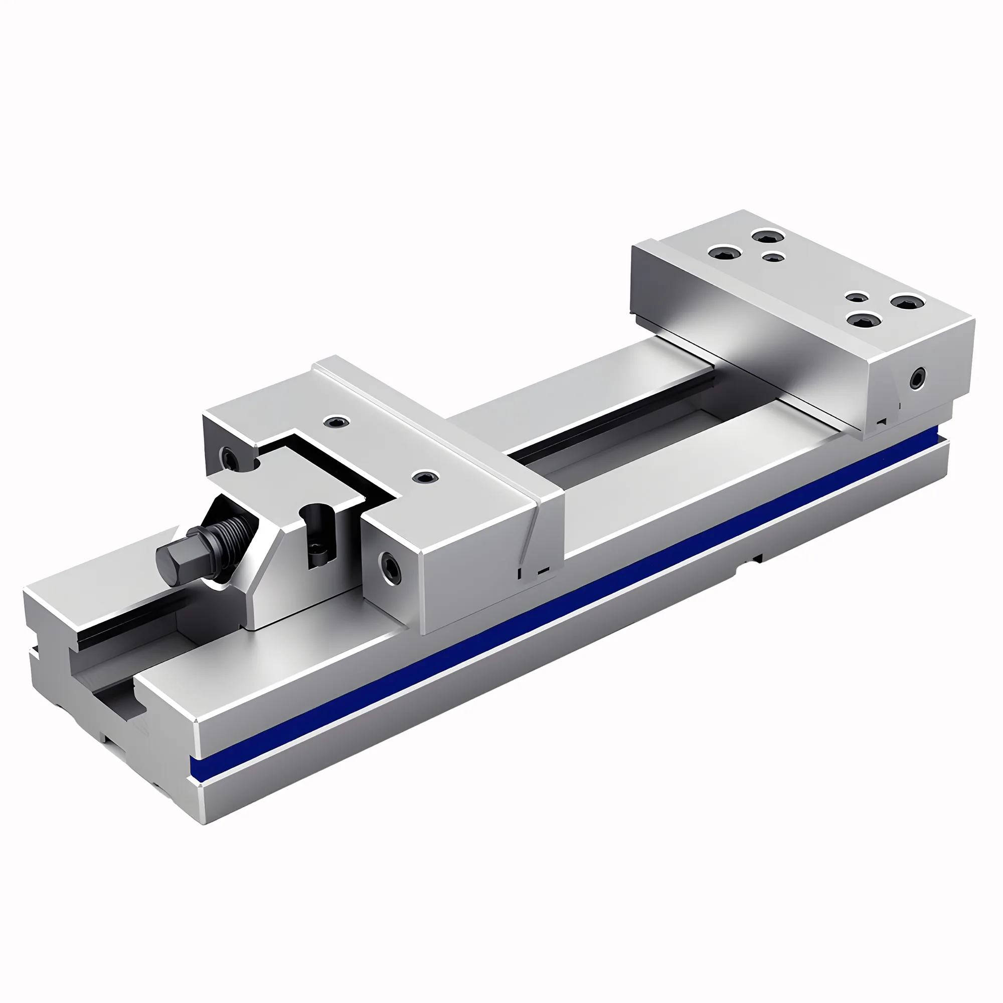
Precision modular vises — vises that accept interchangeable jaws with ±0.01 mm repeatability — bridge the gap between zero-point pallet systems and part-specific hard fixtures. A modular vise on a zero-point sub-plate delivers the repeatability of a dedicated fixture at 30–60% lower tooling cost for medium-complexity prismatic parts.
Jaw Height and Body Profile
The jaw height selection directly controls the spindle clearance geometry. Standard 40 mm jaw height typically leaves 40–60 mm of vise body above the pallet (varies by vise model), which is compatible with 3+2 (positional 5-axis) but not always with full simultaneous cutting at high tilt angles. Low-profile vises (jaw height 25–30 mm, body height ≤55 mm total) are designed specifically for simultaneous 5-axis environments where the spindle must approach from steep angles.
For round workpieces — shafts, rings, and flanges — a self-centering 3-jaw chuck mounted on a zero-point sub-plate is often preferable to a vise. Self-centering chucks provide 120° symmetrical clamping that naturally centers the rotational axis of the part on the machine table center, simplifying 5-axis program origin setup. Repeat centering accuracy for precision 3-jaw chucks is typically ≤0.01 mm TIR — comparable to zero-point system accuracy for round features.
Vise Orientation on Trunnion Tables
On a trunnion-style 5-axis machine, the vise can be oriented with its clamping axis parallel to the trunnion rotation axis (lateral) or perpendicular to it (axial). Lateral orientation reduces fixture height in the tilt plane and is preferred for parts wider than they are tall. Axial orientation maximizes accessibility to the part top and front faces and is preferred for tall, narrow parts where the critical features are on the long side faces.
✦ Modular Vise Best For
- Prismatic parts, 50–300 mm in length
- Medium-volume production (10–500 parts)
- 3+2 positional and simultaneous 5-axis
- Quick changeover between part families
✦ Zero-Point Pallet Best For
- High-value complex parts requiring full 5-axis access
- Fixturing complex geometries (castings, forgings)
- Multi-machine pallet transfer in cell environments
- Maximum spindle access priority over quick change
Summary
Match clamp geometry to spindle access angle before cutting the first chip.
Effective 5-axis workholding is primarily an interference geometry problem. Use zero-point systems (≤0.005 mm repeat accuracy, 52 or 96 mm grid) for precision multi-setup or pallet-transfer work. Design fixtures with all clamping elements below 60 mm table height and observe a 30 mm perimeter exclusion zone. Orient parts so all critical features fall within the ±135° tilt arc from the primary datum. Run kinematic simulation with exact holder models, not generic library proxies, and verify near-misses physically on first article. A fixture that costs an extra 2–3 hours of design time to get the clearance geometry right saves an average of 30–90 minutes per part across the production run.
What is a zero-point clamping system and why is it important for 5-axis machining?
A zero-point clamping system locks precision-ground shanks into spring-loaded receivers in a sub-plate, providing ≤0.005 mm XY repeat positioning accuracy. In 5-axis machining, this accuracy allows workpieces to be moved between setups or machines without re-indicating, holding feature-to-feature tolerances of ≤0.01 mm — critical when a part is too complex to complete in a single clamping.
How do I calculate minimum clearance between a clamp and the spindle?
Use C_min = R_spindle_nose + R_safety + H_feature. For a standard 40-taper spindle (nose radius ~40–50 mm) with 10 mm safety margin, any clamp must stay at least 50–60 mm below the lowest feature the spindle must reach at full tilt. At 90° tilt, the spindle nose sweeps a diameter equal to twice its nose radius, so a 50 mm nose radius clears a 100 mm circle at the part plane.
What is the 270° rule for 5-axis single-setup machining?
The 270° rule states that all part features must fall within a ±135° tilt arc (270° total) from the primary datum orientation to be machined in one setup. Most trunnion 5-axis machines tilt from −30° to +105° — features outside this arc require a second setup or an inclined fixture. Correct part orientation typically reduces inaccessible features from 20–30% (random orientation) to under 5%.
When should I use a modular vise versus a zero-point pallet for 5-axis work?
Use a modular vise for prismatic parts in the 50–300 mm range where 3+2 or limited simultaneous 5-axis is sufficient — cost is 30–60% lower than a dedicated pallet fixture. Use a zero-point pallet when the part requires full simultaneous 5-axis access from steep angles, when the fixture must transfer between machines, or when the part complexity justifies a lower profile fixture to maximize spindle clearance.
How does clamp height affect spindle access in 5-axis machining?
Clamp height directly limits the maximum tilt angle at which the spindle can approach the workpiece. A clamp rising 60 mm above the table blocks all approaches within the cone swept by the spindle nose at full tilt (typically ±90°). Low-profile zero-point sub-plates (28–50 mm height) keep the entire clamping system below the minimum clearance threshold for most 5-axis simultaneous operations, compared to 80–120 mm for conventional step-block setups.
Sources
- Schunk Zero-Point Clamping Systems — VERO-S Product Documentation
- DIN 69893 — Hollow Shank Taper (HSK) Geometry for Tool Holders
- ISO 10791 — Test Conditions for Machining Centres
- Machinery's Handbook 31st Edition — Jigs and Fixtures Chapter
- SME Fundamentals of Tool Design, 6th Edition — 5-Axis Fixturing