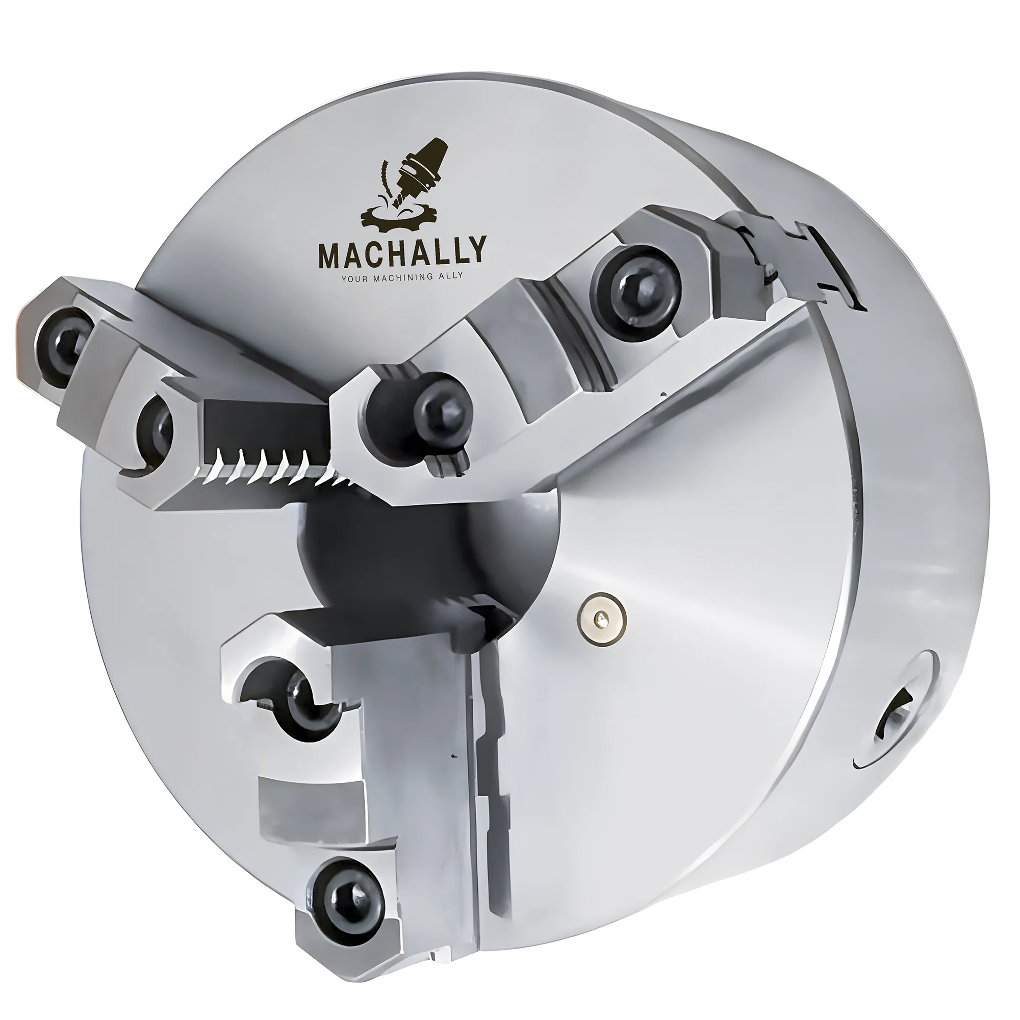
Soft jaws cut in-situ on a three- or four-jaw chuck can hold irregular or pre-machined workpieces to ≤0.02 mm TIR repeatability — provided the bore is machined at the correct clamping load and the locating step or radius matches the part geometry within 0.05 mm. Select AISI 1018 mild steel for most turning jobs (HRC 15–20, machines easily, re-bores readily), 6061-T6 aluminum for light finishing cuts on delicate surfaces, and AISI 4140 pre-hardened (HRC 28–32) for high-production runs where jaw wear exceeds one set per week under typical shop conditions.
Quick Soft Jaw Reference
| Problem / Goal | Primary Action | Expected Impact |
|---|---|---|
| Part shifts between setups | Bore jaws with part-diameter offset +0.0–0.05 mm and add a locating step | TIR repeatability ≤0.02 mm across re-chucks under typical conditions |
| Jaws wear out in < 1 week | Switch from 1018 steel to 4140 pre-hardened (HRC 28–32) | Jaw life 3–5× longer in continuous production runs |
| Soft aluminum part marks visible after clamping | Switch from steel to 6061-T6 aluminum soft jaws | Marring eliminated at clamping forces up to ~5 kN on 150 mm jaws |
| Bore diameter bored too tight; part won't enter | Re-bore at correct load using a sacrificial ring or scrap piece at final clamping torque | Eliminates spring-back distortion that can add typically 0.03–0.10 mm bore taper |
| Irregular casting or forging drifts under cut | Add a radius pocket matching the part's OD + step shoulder for axial stop | Eliminates axial drift; typical position repeatability ±0.05 mm when soft jaws are bored in-situ on the production chuck |
| High-production run needs quick jaw change | Pre-bore a second set at the same diameter; use chuck body register for jaw re-seating | Change time under 3 minutes with register-seated jaw systems |
Minimum 4 rows. Expected Impact is quantified with boundary conditions.
Why Soft Jaws Outperform Hard Jaws for Irregular Parts
Soft jaws are the preferred workholding method for irregular, pre-machined, or delicate workpieces because they conform the locating surface to the part geometry rather than requiring the part to conform to the jaw.
Standard hard jaws on a three-jaw chuck grip on three tangential contact lines. For round bar stock this is acceptable — the error is limited to jaw runout (typically 0.05–0.15 mm TIR on a production chuck per ISO 3442 tolerance class 3). For a casting with a rough OD, a pre-machined bore, or a profiled surface, three tangential contact points generate unpredictable deflection forces that shift the part axially and radially.
Soft jaws machined in-situ eliminate the contact-line problem. When bored to match the part diameter, the contact area expands from three line contacts to three arc contacts spanning typically 15–25° of jaw face, distributing clamping force across a much larger area. A soft jaw arc contact spanning 20° on a 100 mm diameter distributes force over approximately 17 mm² of contact area per jaw — roughly 8–12× the contact area of a line contact on the same diameter.
For a K11 three-jaw self-centering chuck, the scroll mechanism self-centers the jaws simultaneously, so boring all three jaws in one pass ensures all three bore arcs are concentric with the spindle axis. For a K12 four-jaw self-centering chuck, the same principle applies: boring all four jaws simultaneously at clamping load ensures the locating geometry aligns to the spindle centerline, not to the individual jaw travel paths. For a comparison of when to use three-jaw versus four-jaw chucks, see the 3-jaw vs 4-jaw lathe chuck selection guide.
ISO 3442 defines the chuck body register (the rabbet that locates jaw sets) — this is the geometric reference that soft jaw systems rely on to maintain repeatability when jaws are swapped between setups.
Material Selection: 1018, 6061, or 4140?
The three most common soft jaw materials differ in machinability, wear life, and surface protection:
AISI 1018 steel is the default choice for general-purpose turning because it balances machinability, re-boreability, and adequate wear life for most job-shop operations. A set of 1018 soft jaws typically lasts 50–200 re-bores depending on jaw depth, clamping load, and workpiece material before the jaw body becomes too thin to re-use.
6061-T6 aluminum is preferred for thin-wall and pre-finished workpieces because its low hardness prevents surface marking at clamping forces below approximately 5 kN on 150 mm chuck jaws. The trade-off is accelerated wear: aluminum jaws on a production run of steel parts deform after 20–50 cycles under typical roughing loads. 6061-T6 aluminum soft jaws are used for finish-turning delicate surfaces because they prevent marring while still conforming to ±0.02 mm of the bored diameter.
AISI 4140 pre-hardened (HRC 28–32) is used for high-production runs where 1018 jaws wear in fewer than five days of continuous use. The harder matrix resists deformation under clamping forces above 8 kN and maintains bore geometry longer. Machining 4140 at HRC 30 requires flood coolant and TiAlN-coated carbide at reduced speeds (typically 80–120 m/min) to prevent rapid tool wear. TiAlN coatings are preferred for boring pre-hardened steel soft jaws because their oxidation resistance above 800°C sustains cutting performance at the elevated temperatures generated when machining HRC 28–32 steel, extending insert life 2–4× compared to uncoated carbide under typical dry or light-flood conditions. AISI 4140 pre-hardened soft jaws extend jaw life 3–5× compared to 1018 in continuous production, but increase boring setup time by 30–50% due to lower machinability.
Material Selection Decision Rule
Use 1018 for prototype and job-shop work (< 5 parts/day), 6061-T6 for delicate or pre-finished surfaces, and 4140 pre-hardened when the same jaw set is used for > 50 consecutive cycles with clamping forces > 8 kN.
Boring the Jaws: Load Compensation and Diameter Offset
The most common soft jaw failure is boring at zero load and then clamping the part at full torque. Scroll and cam-actuated chucks deflect radially under clamping load — typically ~0.03–0.10 mm per jaw on 150–200 mm chuck bodies, varying with chuck condition and load — which causes the bored diameter to close slightly when the workpiece is removed and the jaws re-engage.
The correct procedure is to bore the jaws while they are loaded against a sacrificial ring or a scrap piece of the same diameter at the final clamping torque. This pre-loads the jaw mechanism to match the deflection state of the actual clamping condition.
Bore diameter offset guideline (applies to most chuck types under typical loads):
| Chuck Body Diameter | Clamping Load (typical) | Bore Offset (jaw relaxed → clamped) |
|---|---|---|
| 100 mm (3-jaw scroll) | 2–4 kN per jaw | 0.02–0.05 mm |
| 150 mm (3-jaw scroll) | 3–6 kN per jaw | 0.03–0.07 mm |
| 200 mm (3-jaw power) | 5–10 kN per jaw | 0.04–0.10 mm |
| 250 mm (4-jaw scroll) | 4–8 kN per jaw | 0.03–0.08 mm |
Values are typical industry ranges based on scroll-type chuck geometry; verify on your specific chuck body by measuring bore diameter at zero load vs. rated load.
The sacrificial ring method: chuck a piece of scrap stock at rated clamping torque, bore the jaws to the part diameter, then remove the scrap. The jaws will spring open by the offset amount. When the actual part is clamped at the same torque, the jaws close back to the bored diameter and achieve the desired contact geometry.
Boring the jaws without load pre-compensation is the primary cause of poor soft jaw repeatability — the resulting bore taper of typically 0.03–0.10 mm (varies with chuck size, load, and condition) means the part seats on the jaw edges rather than on the arc contact zone.
Avoid This
Never bore soft jaws to the final diameter in one plunge at full depth. Use two passes: a roughing pass typically 0.3–0.5 mm undersize, then a finish pass at the target diameter. A single heavy plunge pass can create 0.05–0.15 mm of bore taper due to boring bar deflection and chip interference, especially in 1018 steel at high feed rates.
Locating Features: Steps, Radii, and Axial Stops
A soft jaw with only a plain bore can hold diameter but cannot prevent axial shift; adding a locating step or shoulder eliminates axial drift and reduces part-to-part length variation to typically ±0.05 mm under stable conditions.
Three locating geometries are used in practice:
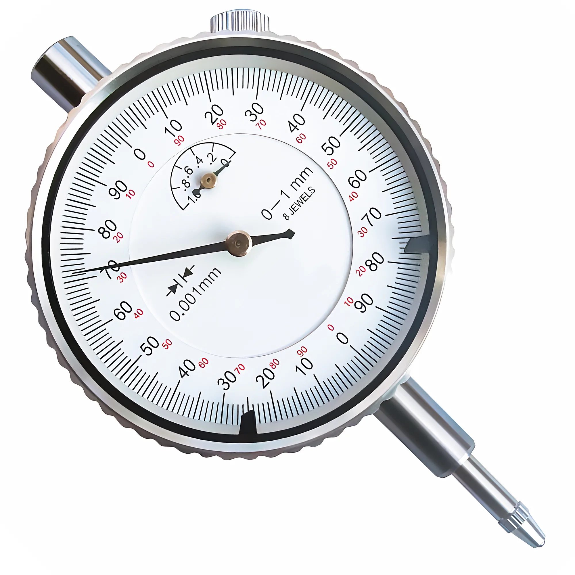
Step shoulder (most common): Machine a typically 1–3 mm deep step at the bore bottom that matches the shoulder diameter on the workpiece. The part rests on this step and is located both radially (by the bore) and axially (by the step face). For the step to be effective, the step face must be square to the spindle axis within 0.02 mm — check with a dial indicator on the step face before using the jaws in production.
Radius pocket: For round castings or forgings with no square shoulder, machine a radius pocket matching the part's OD at the bore depth. The radius pocket provides a three-point axial and radial nest. A radius pocket bored to match the workpiece OD within 0.05 mm provides axial repeatability of ±0.05–0.10 mm and radial TIR ≤0.03 mm in typical production conditions.
Contoured pocket for irregular geometry: For non-round profiles (hex stock, flanged parts, D-section shafts), the soft jaw can be contoured by machining the jaw face on a milling center before fitting to the chuck. This requires the jaw mounting interface (T-slot or serrated base) to provide a repeatable jaw-to-chuck register — the ISO 3442 chuck body register is the reference datum. When the jaw serration pitch matches the chuck body (typically 1.5 mm or 3.0 mm pitch), re-seating error is typically < 0.05 mm. DIN 55029 defines the spindle nose flange connections used on manual and CNC lathes, and chucks that comply with DIN 55029 provide a standardized locating register that ensures jaw sets can be transferred between compliant machines without loss of repeatability — a key advantage when multiple lathes run the same part family.
Clamping Force and the Minimum Gripping Force Calculation
For irregular or non-round workpieces, the cutting torque must not exceed the frictional grip available from the clamping system. The minimum required clamping force for turning is derived from balancing the cutting torque against the friction moment at the jaw contact area.
The simplified grip force check for turning:
F_clamp ≥ (2 × M_c) / (D_w × μ × N_j)
Where:
- F_clamp = clamping force per jaw (N)
- M_c = cutting moment at the workpiece (N·mm) = F_tangential × D_w/2
- D_w = workpiece diameter (mm)
- μ = friction coefficient between jaw and workpiece (0.12–0.18 for steel-on-steel soft jaws; 0.08–0.12 for aluminum jaws)
- N_j = number of jaws (3 for K11; 4 for K12)
At equal total chuck force, friction-derived slip resistance is independent of jaw count — each jaw shares the load proportionally, so total friction = F_total × μ regardless of whether 3, 4, or 6 jaws contact the workpiece. The four-jaw (K12) advantage on irregular parts is geometric, not frictional: four contact points stabilize asymmetric or non-round profiles against rocking, while three contact lines on an out-of-round forging can develop unequal load distribution that drives the part off-center under cut.
Worked example: 100 mm diameter steel part, tangential cutting force 800 N, steel 1018 soft jaws (μ = 0.15), K11 three-jaw chuck:
- Cutting moment M_c = 800 × 50 = 40,000 N·mm
- Required F_clamp per jaw = (2 × 40,000) / (100 × 0.15 × 3) = 1,778 N per jaw minimum
- A 150 mm K11 chuck at rated tightening torque typically develops 3,000–5,000 N per jaw, providing a safety margin of 1.7–2.8× under these conditions
The safety factor for interrupted cutting (milling a flat or drilling through) should be at least 2.5×; for continuous turning of smooth ODs, 1.5× is generally acceptable in stable setups. For the full workholding clamping force methodology including friction coefficients and safety factors for different workholding configurations, see the workholding clamping force calculation guide. Irregular workpieces with asymmetric mass generate centrifugal imbalance at high spindle speeds — for parts > 0.5 kg offset by > 10 mm from spindle axis, reduce spindle speed by 20–40% or balance the assembly before exceeding 1,500 RPM.
Minimum Clamping Force for Confidence
Run the grip force calculation before the first cut on any irregular workpiece. If the safety margin at rated tightening torque is less than 1.5×, add an axial stop to reduce the required radial grip by transferring some of the cutting force to the stop face.
Repeatability Testing and Jaw Life Management
After boring soft jaws, test repeatability before committing to a production run. For a detailed dial indicator technique for indicating four-jaw setups, see four-jaw chuck setup and indicating technique. The standard procedure for soft jaw verification:
- Chuck the part at rated tightening torque. Indicate the OD with a 0.001 mm resolution dial indicator. Record runout.
- Remove the part. Re-chuck three times without re-indicating. Record the peak-to-peak TIR variation across all re-chucks.
- If re-chuck variation exceeds 0.03 mm, investigate: inconsistent tightening torque, jaw serration debris, or bore diameter out of tolerance.
Soft jaws bored correctly at clamping load with a locating step typically achieve re-chuck TIR variation of 0.01–0.02 mm for 90% of setups in a clean workshop environment. Jaws that test at > 0.05 mm variation should be re-bored or replaced.
Jaw life indicators (when to re-bore or replace):
- Bore diameter measured at clamping load has grown > 0.1 mm from nominal (contact patch has worn)
- Step face perpendicularity exceeds 0.03 mm (step has worn or shifted from clamping shock)
- Jaw body thickness below locating bore is < 5 mm (risk of jaw fracture under clamping load)
- Surface of jaw bore shows hard spots from previous workpiece material embedded in the softer jaw
A jaw life log — recording the bore date, bore diameter, part number, and number of cycles — is the most reliable way to predict when re-boring is needed and to catch gradual bore growth before it impacts part location accuracy.
Bore at clamping load, match the bore to the part diameter within 0.05 mm, and always add a locating step.
Machine soft jaws with the chuck pre-loaded against a sacrificial ring at rated clamping torque to eliminate spring-back error. Select AISI 1018 for most jobs, 6061-T6 aluminum for delicate surfaces, and AISI 4140 pre-hardened for high-production runs exceeding 50 cycles per week at clamping forces above 8 kN. Add a 1–3 mm locating step or radius pocket to provide axial location to ±0.05 mm. Verify clamping force against the grip force equation before the first cut on irregular workpieces, and maintain a jaw life log to catch bore growth before it degrades part location accuracy.
Sources
- ISO 3442: Lathe chucks — Dimensions and inspection (ISO)
- DIN 55029: Lathe chuck flange connections (DIN)
- Machinery's Handbook 31st Edition — Turning and Boring, Workholding (Industrial Press)
- Sandvik Coromant — Chuck workholding in turning operations (Sandvik)
- SCHUNK Chuck Technology: Clamping Force and Jaw Design (SCHUNK)
What material should I use for soft jaws on a lathe chuck?
AISI 1018 mild steel (HRC 15–20) is the standard choice for general-purpose turning — it machines easily, can be re-bored multiple times, and provides adequate wear life for most job-shop runs. Use 6061-T6 aluminum for delicate or pre-finished surfaces to prevent marring at clamping forces up to ~5 kN. Switch to AISI 4140 pre-hardened (HRC 28–32) when jaw sets wear out in under a week of continuous production use.
Why must soft jaws be bored at clamping load?
Boring at zero load and clamping at full torque causes the jaw mechanism to close by 0.03–0.10 mm (depending on chuck size and load), producing a bore taper that seats the part on jaw edges rather than on the arc contact zone. Pre-loading the jaws against a sacrificial ring at rated torque while boring compensates for this spring-back and achieves the correct bore geometry at the actual working clamping condition.
What TIR repeatability can I expect from correctly bored soft jaws?
Soft jaws bored at clamping load with a locating step achieve re-chuck TIR variation of 0.01–0.02 mm for 90% of setups in a clean workshop environment. Without a locating step (bore only), axial drift adds variability; with a step and correct bore diameter (within 0.05 mm of part diameter), total positional repeatability is typically ≤0.02 mm TIR under stable conditions.
How do I calculate the required clamping force for an irregular workpiece?
Use the simplified grip check: F_clamp per jaw ≥ (2 × M_c) / (D_w × μ × N_j), where M_c is the cutting moment (tangential force × workpiece radius), D_w is workpiece diameter, μ is jaw friction coefficient (0.12–0.18 for steel jaws), and N_j is jaw count. The calculated minimum should be ≤60% of rated chuck clamping force to maintain a safety margin of at least 1.5× for continuous turning, or 2.5× for interrupted cutting.
When should I add a locating step to soft jaws?
Add a locating step whenever axial position accuracy matters — typically any part requiring a turned shoulder, face, or groove to be within ±0.1 mm of a datum face. A typically 1–3 mm deep step matching the workpiece shoulder diameter controls both radial and axial location, reducing axial drift from several tenths of a mm (bore only) to typically ±0.05 mm. Check the step face perpendicularity with a dial indicator to ≤0.02 mm before committing to production.