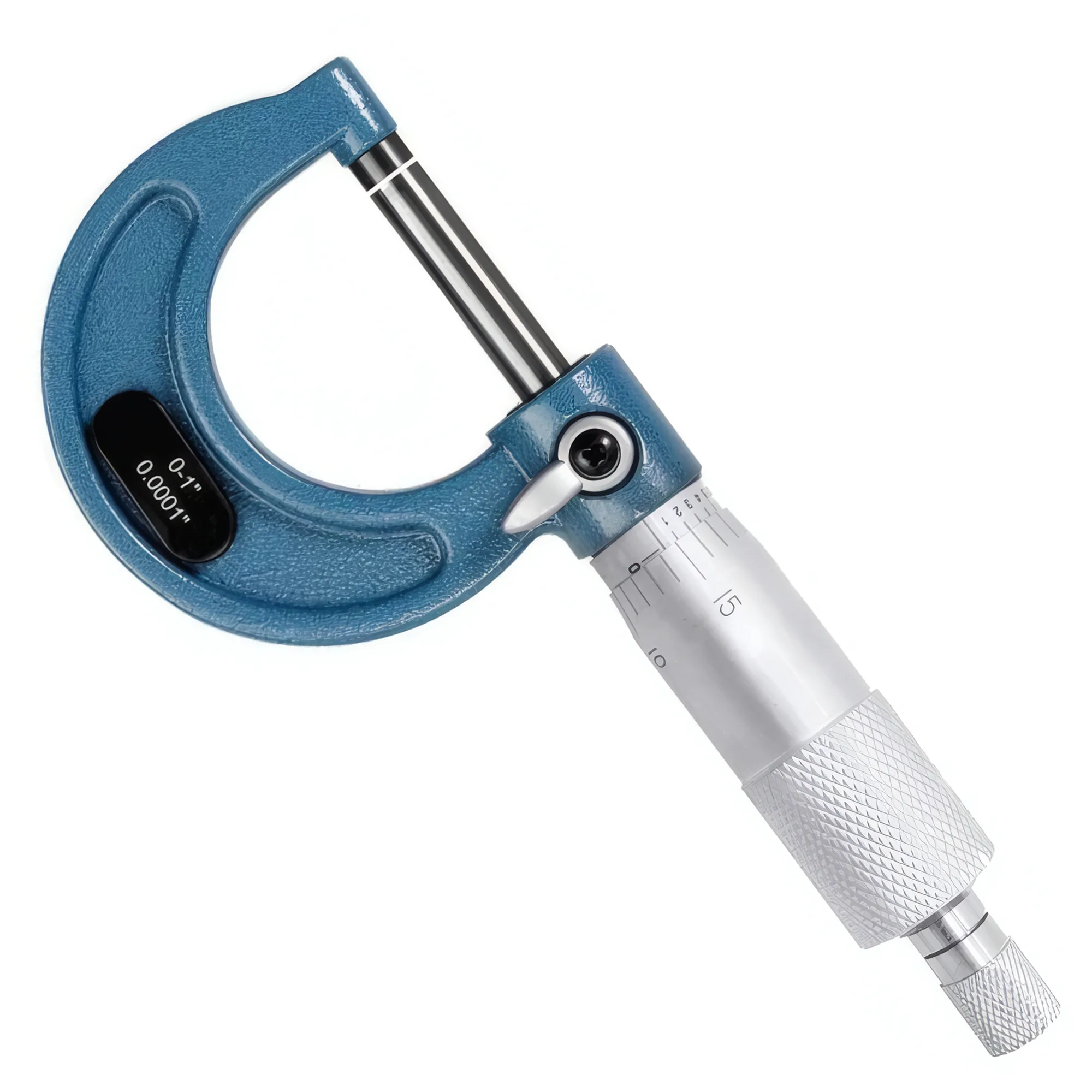
An outside micrometer that has not been verified against a calibrated gauge block will drift outside its ±0.004 mm accuracy specification (DIN 863-1 / ISO 3611:2023, 0–25 mm range) within months of daily shop use. Verify zero at room temperature (20 °C ± 1 °C), check against a Grade 1 gauge block at mid-range, and adjust the barrel if error exceeds half the tolerance band — these three steps recover full traceability in under five minutes.
Quick Micrometer Maintenance Reference
| Problem / Goal | Primary Action | Expected Impact |
|---|---|---|
| Zero error after thermal soak | Re-zero with faces clean, at 20 °C for ≥ 30 min | Eliminates thermal drift error of 0.002–0.005 mm |
| Mid-range reading offset ≥ 0.003 mm | Verify with calibrated gauge block; adjust barrel lock nut | Restores accuracy to within ±0.002 mm of nominal |
| Ratchet slipping or inconsistent feel | Clean and re-tension ratchet pawl spring; replace if worn | Reduces measurement scatter from ±0.005 mm to ±0.001 mm |
| Spindle rough or sticky motion | Clean spindle threads and thimble bore with lint-free cloth; apply thin spindle oil | Smooth travel with < 1 N actuation force |
| Anvil or spindle face pitting | Lap with figure-eight motion on grade lapping plate until flat within 0.0003 mm | Eliminates seating error that can exceed 0.010 mm on pitted faces |
| Long-term storage corrosion | Apply rust-preventive oil film; store in padded case with silica gel | Prevents corrosion-induced face distortion > 0.005 mm |
Understanding Micrometer Accuracy and Why It Drifts
An outside micrometer in daily shop use loses calibration for three primary reasons: thermal expansion of the frame, mechanical wear of the lead screw, and contamination on measuring faces.
DIN 863-1 (adopted as ISO 3611:2023) specifies that a 0–25 mm outside micrometer must achieve a maximum permissible error (MPE) of ±0.004 mm across its full measuring range at 20 °C. For instrument selection criteria and accuracy-class comparisons, see the micrometer and dial indicator selection guide. For a 25–50 mm instrument, the MPE is ±0.005 mm. These tolerances assume clean, undamaged measuring faces, consistent ratchet torque, and measurements taken after thermal equilibration with the instrument.
The lead screw pitch on a standard micrometer is 0.5 mm per revolution. One full thimble revolution therefore equals exactly 0.5 mm of travel. The thimble scale divides this into 50 divisions, each representing 0.01 mm. Any looseness or contamination in the lead screw translates directly into a linearity error that accumulates across the range. A worn lead screw showing 0.003 mm of backlash at mid-range will cause measurement errors up to 0.006 mm even after correct zeroing.
Thermal expansion is the most commonly underestimated source of error. The coefficient of thermal expansion for hardened tool steel is approximately 11–13 µm/m·°C. For a 25 mm outside micrometer frame, a 5 °C rise from baseline (common when holding the instrument in a warm hand) introduces a length change of 1.4–1.6 µm — already a meaningful fraction of the ±0.004 mm budget. Holding the frame insulated handles, or using a stand fixture, keeps thermal contribution below 0.001 mm in typical shop environments.
Gauge Block Verification Procedure
Grade 1 gauge blocks (ISO 3650) with a deviation tolerance of ±0.10 µm at 20 °C are the correct reference for verifying outside micrometers in production environments.
The verification procedure follows a structured sequence that isolates each error source:
Step 1 — Thermal equilibration. Place the micrometer and gauge blocks on a clean granite surface plate and allow at least 30 minutes for temperature stabilization. Both instrument and blocks must reach room temperature (target: 20 °C ± 1 °C). A 1 °C deviation between instrument and gauge block introduces a differential expansion error of approximately 0.3 µm on a 25 mm reference — negligible alone but additive with other sources.
Step 2 — Clean the measuring faces. Wipe the anvil and spindle faces with an optical-grade lens cloth or clean chamois. Any abrasive particles trapped between faces during closure will scratch the measuring faces and permanently elevate the face-to-face error. Do not use shop towels — they deposit lint fibres that read as 1–3 µm offsets.
Step 3 — Zero check. Close the spindle onto the anvil using the ratchet thimble only (never the main thimble barrel by hand). The ratchet mechanism limits applied force to approximately 5–10 N — the standardized clamping force that produces consistent screw engagement. The ratchet stop should click 2–3 times before reading; a single click indicates insufficient engagement and under-reads by up to 0.003 mm. If the thimble line does not align with the datum line within ±0.001 mm (one-tenth of a graduation), adjust the barrel using the barrel lock nut wrench supplied with the instrument.
Step 4 — Mid-range gauge block check. Select a gauge block nominally equal to the mid-range of the micrometer (e.g., 12.5 mm for a 0–25 mm instrument). Apply the gauge block between faces using the ratchet stop. Record the reading. Repeat three times and average. The average should fall within ±0.002 mm of the gauge block nominal. Errors between 0.002 mm and 0.004 mm indicate an instrument approaching its MPE limit — schedule recalibration. Errors above 0.004 mm require immediate service.
Step 5 — Full-range linearity spot check. For critical applications, verify at three points: ~25% range (e.g., 6.5 mm), 50% (12.5 mm), and ~75% (19.5 mm). A consistent offset across all points indicates a zero error correctable by barrel adjustment; a varying offset indicates lead screw wear or a bent frame requiring professional recalibration.
Gauge Block Wringing for Better Contact
Wring two gauge blocks together to achieve a combined size (e.g., 1.0 mm + 12.5 mm = 13.5 mm) rather than sourcing single blocks for every check point. Proper wringing using a figure-eight sliding motion reduces the air gap between blocks to under 0.025 µm, contributing negligible error to the verification.
Ratchet Mechanism Adjustment and Torque Consistency
The ratchet thimble is not a convenience feature — it is the standardized torque limiter that makes micrometer readings reproducible to within ±0.001 mm between different operators.
ISO 3611:2023 specifies that micrometer calibration and verification are performed using the ratchet stop at a defined measuring force. Without consistent ratchet engagement, the applied closing force varies by operator and session, directly varying the spindle thread engagement depth and causing reading scatter up to ±0.005 mm for a micrometer with a slight amount of lead screw play.
A ratchet mechanism in proper condition exhibits these characteristics:
- Clicks 2–3 times before the pawl disengages under load
- Consistent resistance with no grinding, skipping, or sudden release
- Positive lockup — once clicked, the reading does not change when lateral load is applied to the thimble
Ratchet adjustment procedure:
If the ratchet slips with fewer than two clicks, the pawl spring tension is insufficient. Most micrometers use a coil or leaf spring beneath the pawl. Access by removing the ratchet cap (typically a 0.5–1 mm hex set screw or friction press-fit). Clean the pawl seat and spring channel with isopropyl alcohol. If the spring is plastically deformed (not returning to its free length), replace it — a worn spring cannot be re-tensioned reliably. Replacement springs are standardized by frame size (most manufacturers use one of three sizes for 0–25 mm through 50–75 mm instruments). After reassembly, verify that the click force feels consistent across five consecutive closures on the same zero reference block.
If the ratchet binds or grinds, disassemble and inspect the ratchet teeth for burred edges. Polish burrs with 600-grit emery paper on a flat lapping plate, keeping strokes perpendicular to the tooth direction. Burrs typically form from dropping the instrument onto the thimble end — a force of as little as 0.5 m drop height produces peak impacts of 50–100 G that permanently deform the soft brass ratchet components.
Do Not Use the Barrel to Force Closure
Closing the spindle by gripping and rotating the barrel directly (bypassing the ratchet) applies uncontrolled axial force up to 50–100 N — 10× the intended measuring force. This overloads the lead screw thread flanks, accelerating wear and permanently increasing backlash. After repeated barrel-forced closures, micrometers typically show 0.003–0.008 mm of hysteresis that is unrepairable without lead screw replacement.
Barrel Adjustment for Zero Error Correction
Zero error in an outside micrometer is correctable without tools beyond the spanner wrench supplied with the instrument, provided the error is within ±0.025 mm (half a graduation).
When the zero check (Step 3 of the verification procedure) shows a consistent offset, adjust as follows:
- Hold the thimble stationary and insert the spanner wrench into the barrel notches (typically two or three notches at the thimble-barrel interface).
- Rotate the barrel in the direction that moves the datum line to align with the thimble zero line. One complete barrel rotation equals 0.5 mm of apparent correction — for small errors (±0.003 mm), only a few degrees of barrel rotation are needed.
- Re-close on the reference anvil using the ratchet and re-check. Iterate in sub-degree increments until the zero reads within ±0.001 mm.
For errors exceeding ±0.025 mm (more than 2.5 graduations), do not attempt barrel adjustment. This magnitude of error indicates an underlying mechanical issue — lead screw wear, frame distortion, or a damaged measuring face — that barrel rotation will not resolve and may mask. Send the instrument for professional recalibration and service.
The barrel adjustment procedure assumes the measuring faces are undamaged and flat. Before adjusting, verify face flatness by wringing an optical flat (or Grade 0 gauge block) against each face individually and checking for a monochromatic fringe pattern under sodium light. Faces showing more than one fringe of non-flatness (approximately 0.3 µm) require lapping before zero correction is meaningful.
Spindle and Face Care
Scratched or pitted measuring faces introduce seating errors that cannot be corrected by zero adjustment — they are a geometry error, not a scale error.
The measuring faces of an outside micrometer are hardened to approximately 60–65 HRC and lapped to flatness within 0.0003 mm (0.3 µm). Any abrasive particle larger than this tolerance that enters the contact zone during a measurement creates a local high spot that artificially elevates the reading. Even a single 1 µm aluminium oxide particle from machined swarf trapped between faces adds 0.001 mm to every subsequent measurement until removed.
Routine face care protocol:
- Before each measurement session, wipe faces with an optical cloth — never abrasive shop paper.
- After each measurement session in a contaminated environment (grinding, casting, powder metallurgy), clean faces with isopropyl alcohol on an optical cloth.
- Inspect faces monthly under 10× magnification. Any visible scratch parallel to the measurement direction introduces a positive seating error. Perpendicular scratches and minor surface marks are less critical but indicate face degradation.
For pitted or scratched faces, professional face lapping restores flatness at a fraction of instrument replacement cost. Shop lapping (figure-eight motion on a diamond lapping plate) is viable only if the operator has experience maintaining face parallelism — uneven lapping removes more material from one side, introducing parallelism error that appears as a range-dependent reading offset.
The spindle threads require a thin film of spindle oil (ISO VG 7 or equivalent light instrument oil) applied every 3–6 months under normal use, more frequently in dusty or coolant-mist environments. Do not apply general-purpose machine oil to micrometer spindles — viscosity above ISO VG 10 traps swarf in the thread flanks and causes intermittent stiction that reads as ±0.002–0.004 mm scatter.
Storage Best Practices
An outside micrometer stored with faces touching will develop a permanent zero error from creep stress in the measuring faces over weeks to months, particularly in instruments with carbide-tipped faces.
The correct storage position: close the spindle to within 0.5–1.0 mm of the anvil, leaving a small gap. Most quality micrometers include a storage clamp or a foam insert in the carrying case with a gap built in. Storing with faces touching at temperature or humidity extremes is the single most common cause of the 0.002–0.005 mm permanent zero errors seen in production shop instruments.
Storage environment guidelines:
| Storage Condition | Impact | Recommendation |
|---|---|---|
| Temperature fluctuation ±10 °C/day | Frame distortion cycles; 0.001–0.003 mm range error after 6 months | Store in temperature-stable cabinet; avoid near heaters or windows |
| Humidity > 70% RH | Surface oxidation on non-stainless faces; 0.001–0.002 mm face error after 3 months | Include silica gel desiccant packet in case; replace every 6 months |
| Faces touching in storage | Stress-creep zero drift 0.002–0.008 mm after 1–3 months | Always store with 0.5–1.0 mm gap between faces |
| Stacked unprotected in drawer | Frame impact damage; spindle thread damage from contact with other tools | Individual padded cases or foam inserts required |
| Coolant residue not cleaned | Coolant salts etch measuring faces within 24 h | Wipe and dry immediately after use; apply corrosion inhibitor film |
A light film of rust-preventive instrument oil (e.g., LPS-1 or equivalent) applied to the frame, spindle, and barrel — but NOT to the measuring faces — before extended storage periods provides adequate corrosion protection for up to 12 months in normal workshop environments. Measuring faces should be protected with a separate wax-based face protectant that leaves no residual oil film on the measuring surface.
Outside micrometers used in environments with coolant mist should be wiped, dried, and re-oiled at the end of every shift — coolant formulations containing chlorine or sulfur compounds attack hardened steel faces at a rate of approximately 0.5–1 µm per day of unprotected exposure.
Calibration Interval and Traceability
The appropriate calibration interval for an outside micrometer depends on measurement uncertainty requirements and usage intensity, not on a fixed calendar period.
For production quality control applications requiring measurement uncertainty ≤ ±0.002 mm, calibrate against a traceable gauge block set every 3–6 months or after any event that may have stressed the instrument (dropping, overtightening, use in an extreme temperature environment). For layout and general shop use where ±0.01 mm is acceptable, annual verification is typically sufficient.
ASME B89.1.13 (Micrometers) recommends that shop-level calibration records include: the date, temperature at calibration time, reference gauge block serial number and calibration certificate number, readings at three or more points across the range, and the operator's name. For a broader overview of shop-floor measurement tool selection and tolerance budgeting, see the precision measurement complete guide. Maintaining this simple log enables pattern analysis — an instrument that requires re-zeroing every two months is telling you the lead screw is wearing and will soon exceed MPE even after correction.
Calibration traceability chain for production environments:
- National measurement standard (NIST, PTB, NPL) → Grade K gauge blocks (MPE ±0.05 µm)
- Calibration laboratory → Grade 0 gauge blocks (MPE ±0.05–0.10 µm)
- Production reference → Grade 1 gauge blocks (MPE ±0.10–0.20 µm) — suitable for micrometer verification
- Working gauge blocks → Grade 2 (MPE ±0.20–0.45 µm) — for fixture setup, not micrometer calibration
ISO 3650 is the international standard governing gauge block grades and tolerances. Grade 1 blocks are the appropriate working standard for calibrating micrometers in most production facilities. Grade 2 blocks have tolerances overlapping with the MPE of the micrometer itself and should not be used as calibration references.
Verify zero, check mid-range, and store with a gap.
A five-minute calibration routine — zero check at 20 °C, mid-range gauge block verification, and ratchet function check — maintains outside micrometer accuracy within its ±0.004 mm (0–25 mm, DIN 863-1) specification across months of daily use. Storing with faces 0.5–1.0 mm apart, keeping measuring surfaces clean of abrasive particles, and replacing worn ratchet springs before they cause reading scatter are the three maintenance actions that prevent the majority of micrometer calibration failures in production shops.
Sources
- DIN 863-1 / ISO 3611:2023 — Outside Micrometers — design, tolerances, and verification requirements
- ISO 3650:1998 — Gauge Blocks — length tolerance grades K, 0, 1, 2
- ASME B89.1.13-2013 — Micrometers — design, performance, and calibration requirements
- Mitutoyo Micrometer Calibration Guide — measuring force and ratchet standards
- NIST Calibration of Micrometers — traceability chain and uncertainty evaluation
How often should an outside micrometer be calibrated?
For quality control applications requiring ±0.002 mm uncertainty, verify against a Grade 1 gauge block every 3–6 months or after any drop or thermal shock. For general layout use (±0.01 mm acceptable), annual verification against a traceable gauge block is sufficient. Log every calibration with date, temperature, and block serial number to detect wear trends early.
What causes outside micrometer zero error after storage?
Storing with measuring faces touching is the most common cause — creep stress in hardened faces produces 0.002–0.008 mm permanent zero drift over 1–3 months. Secondary causes include temperature cycling (frame distortion from ±10 °C daily swings) and coolant residue attacking measuring faces. Always store with a 0.5–1.0 mm gap between anvil and spindle.
Can I adjust a micrometer zero error myself?
Yes, for errors within ±0.025 mm (half a graduation). Insert the spanner wrench into the barrel notches, hold the thimble stationary, and rotate the barrel until the thimble zero line aligns with the datum line when closed on the anvil. For errors exceeding ±0.025 mm, the cause is mechanical (lead screw wear or frame damage) — send the instrument for professional recalibration instead.
What gauge block grade is needed to calibrate an outside micrometer?
Grade 1 per ISO 3650 (deviation tolerance ±0.10 µm) is the correct working standard for production shop micrometer verification. Grade 2 blocks (±0.20–0.45 µm) have tolerances too close to the micrometer's own MPE (±0.004 mm for 0–25 mm) to provide a meaningful uncertainty margin and should not be used as calibration references.
Why does the ratchet click count matter during measurement?
The ratchet provides standardized measuring force (5–10 N) that produces consistent lead screw engagement. A single click indicates insufficient engagement and under-reads by up to 0.003 mm. Two to three clicks ensure full thread contact and reproducible results to within ±0.001 mm between operators. Using the barrel directly instead of the ratchet applies 10× the intended force, accelerating lead screw wear.