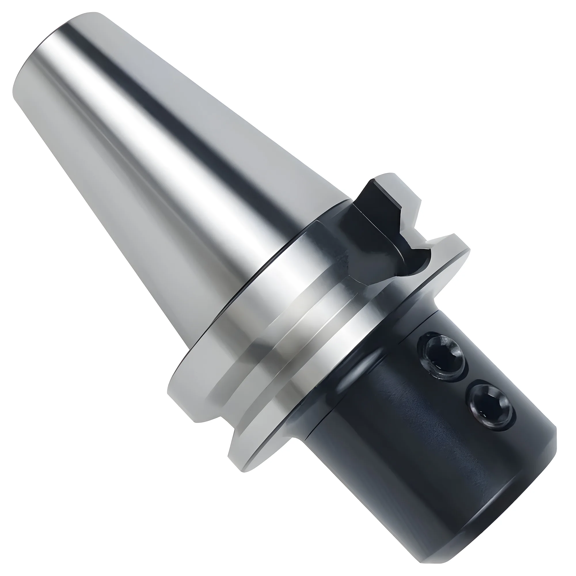
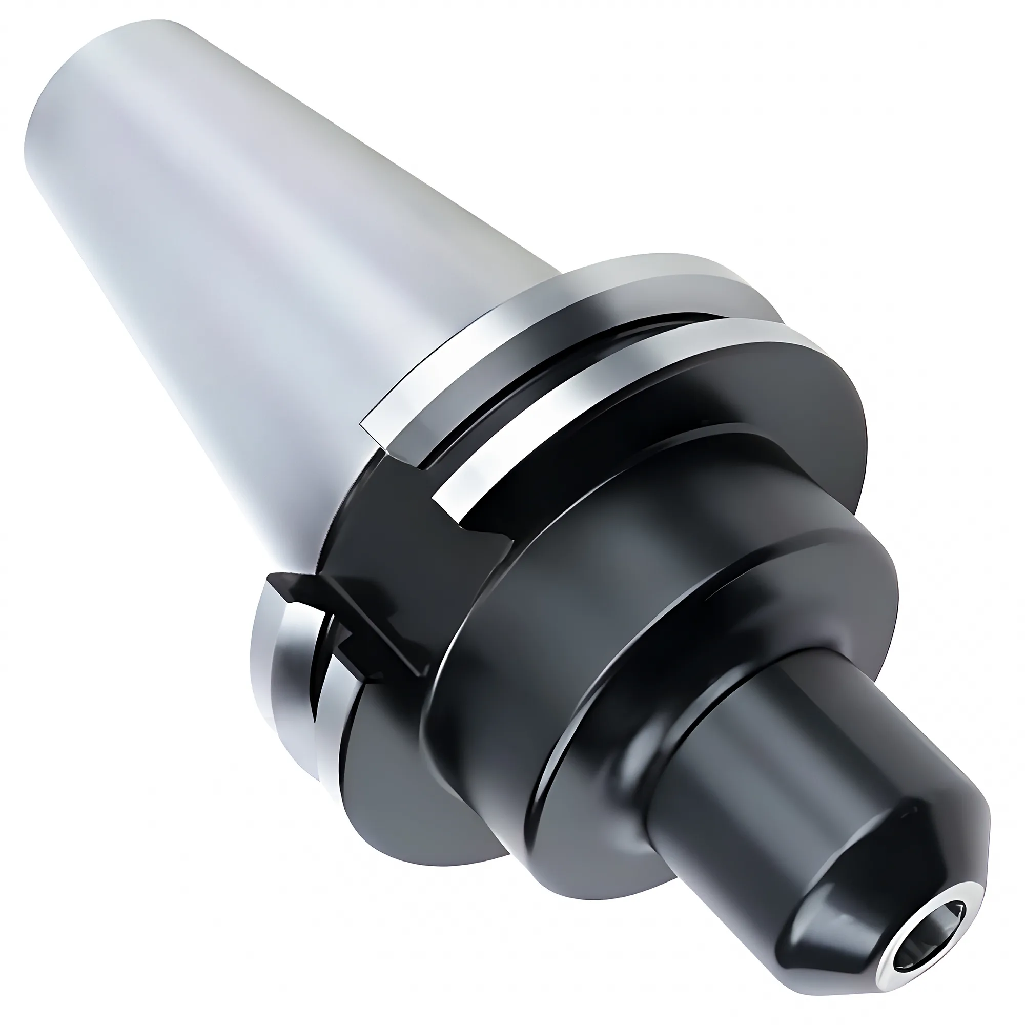
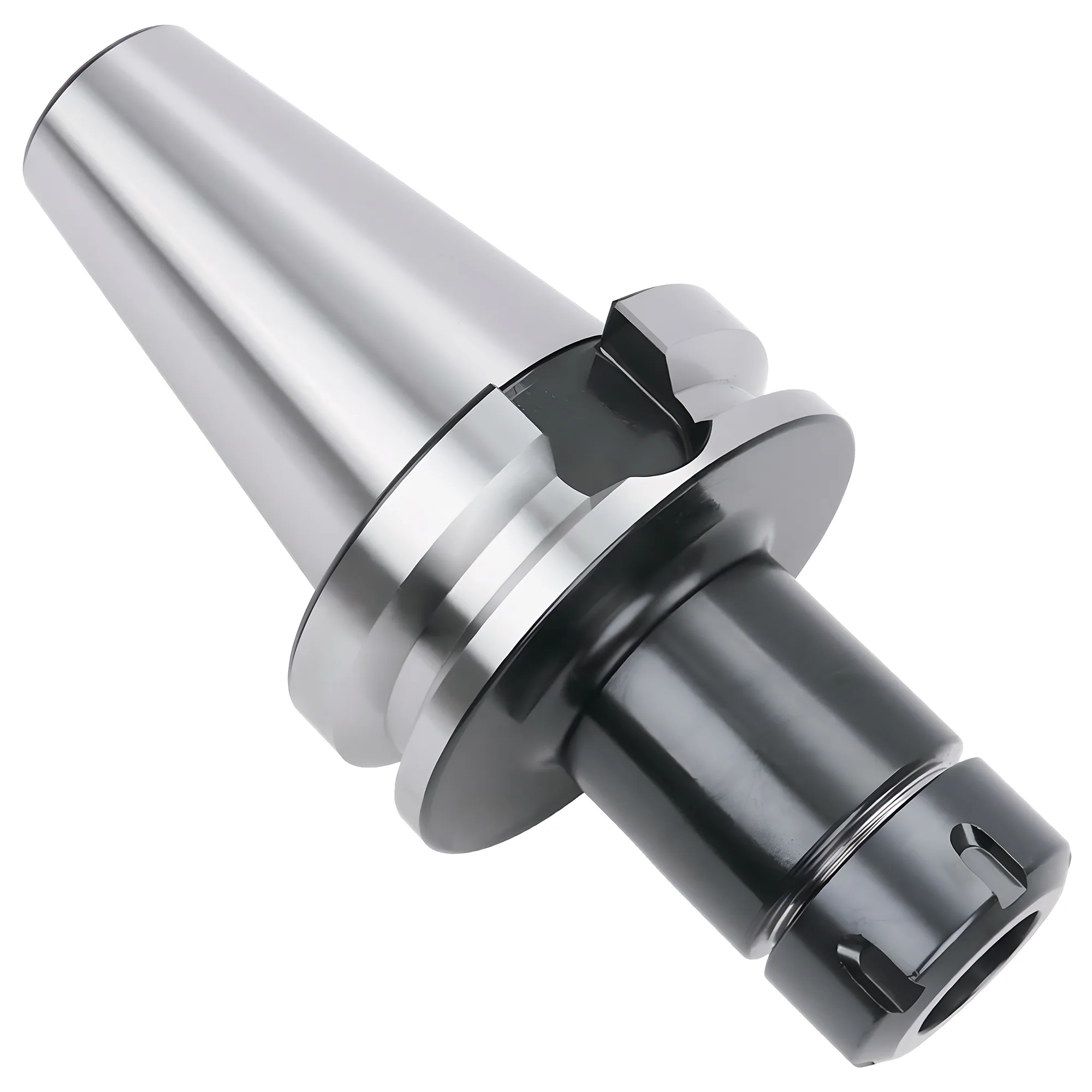
Hold an indexable end mill in a Weldon side-lock holder or a milling chuck when it roughs with interrupted cuts, because a set screw bearing on a DIN 1835 form B flat mechanically blocks pull-out and a roller-type milling chuck typically holds 0.005-0.01 mm TIR with full-circumference grip. Use an ER collet (Class 2, ≤0.020 mm TIR) for light-to-medium work on shanks up to 20 mm (ER32) or 26 mm (ER40), and reserve hydraulic or shrink-fit holders (≤0.003 mm TIR) for indexable finishing, where runout loads one insert harder than the rest.
An insert-carrying cutter body is not a solid end mill with screws on it. Its steel shank is stiffer than its cutting edges are precise, its inserts hit the work one at a time, and its edges already carry pocket-to-pocket height variation before the holder adds any runout of its own. That changes which holder makes sense. For the general holder-family comparison on solid carbide end mills, see the side-lock vs ER vs shrink-fit holder guide; this guide covers straight-shank indexable end mills, high-feed cutters, and the smallest shell-type bodies.
What Makes Indexable Cutters Hard to Hold
Three properties separate indexable bodies from solid carbide tools. Indexable end mills load the holder with repeated impacts rather than a steady force, because each of their 1-5 inserts enters and leaves the cut separately, so pull-out resistance matters more for them than for a solid end mill of the same diameter.
First, the cut is interrupted at the insert level. A 25 mm body with 3 inserts at 1,500 RPM delivers 75 insert entries per second. Each entry is a small hammer blow that the holder grip has to absorb without creeping. Friction-only grips (collets, hydraulic sleeves, shrink-fit bores) resist creep through clamping force alone; a set screw on a flat resists it with geometry.
Second, many indexable shoulder mills use a positive axial rake to cut freely, and the positive axial rake generates an axial force component that tends to draw the cutter out of the holder. In a full-width slot or helical ramp, that pull grows with chip load. A body that walks out 0.1 mm during a roughing cycle leaves a step on the floor and, in the worst case, plunges deeper with every pass until an insert fractures.
Third, the body is steel. Steel has a Young's modulus of about 210 GPa versus 580-620 GPa for cemented carbide, so an indexable body deflects roughly 3× as much as a solid carbide tool of the same diameter and stick-out. Holder choice cannot fix that ratio, but holder gauge length and grip stiffness either add to it or not.
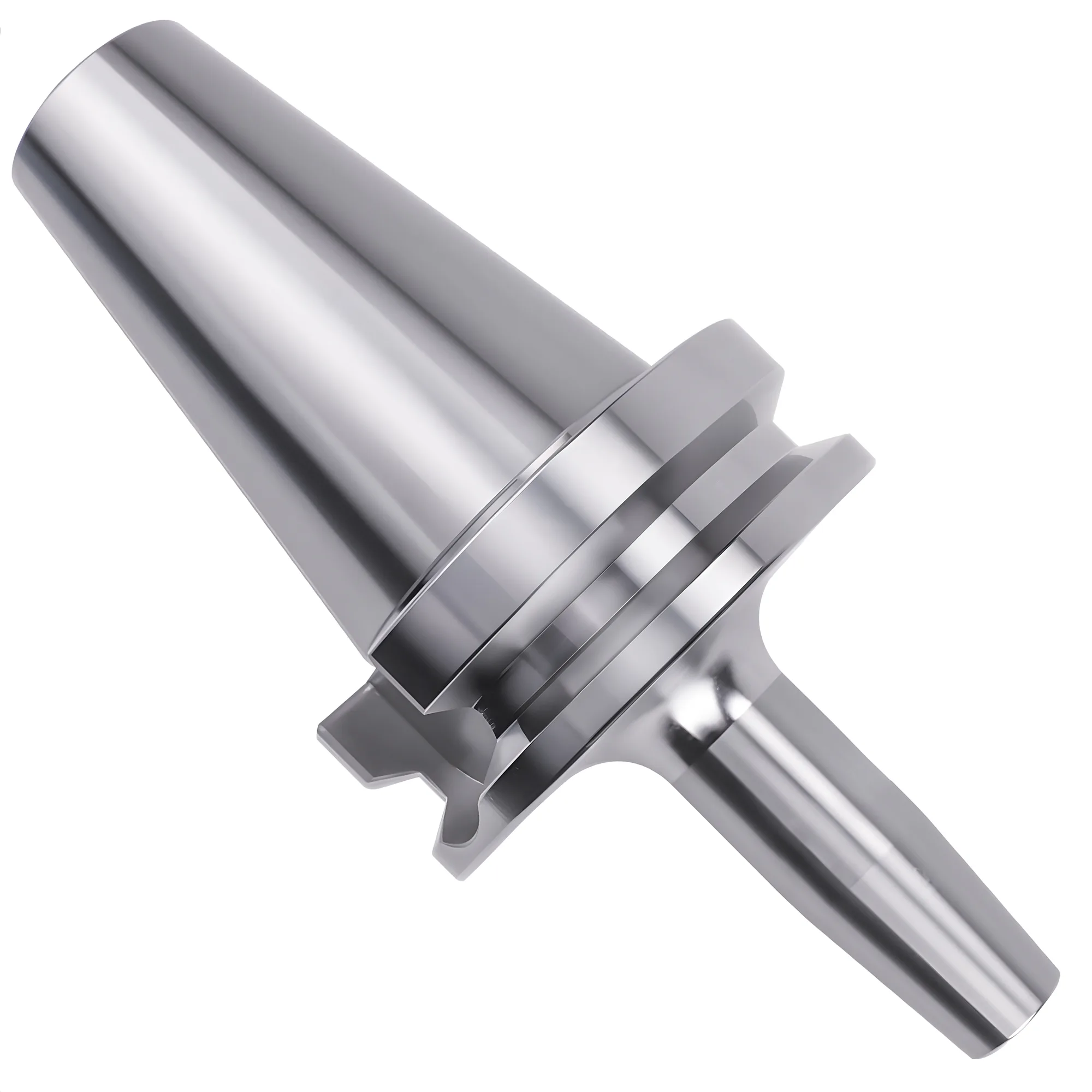
DIN 1835 is the standard most indexable end mill shanks are specified against, because it covers cylindrical shanks for milling cutters regardless of whether the cutting edges are inserts or ground flutes. Form A is the plain cylinder; form B adds the Weldon flat. DIN 6535 defines the equivalent forms (HA, HB, HE) for solid carbide cutters, so it matters here mainly when a carbide-shank indexable body or a carbide extension is in the stack. Choosing the shank form itself (plain vs Weldon vs Whistle-notch) is a separate decision from choosing the holder; this guide assumes the body's shank is already fixed by the cutter maker.
How Each Holder Handles Pull-Out and Interrupted Forces
The five holder families split into two groups: positive (form-locking) drive and friction drive. A side-lock holder (Weldon or Whistle-notch) is the most common holder type that mechanically blocks an indexable body from pulling out, because the set screw bears on a flat that the shank cannot slide past unless the screw loosens or shears.
| Holder | Grip Mechanism | Pull-Out Resistance | Typical Runout (TIR) | Practical RPM | Shank Needed |
|---|---|---|---|---|---|
| Weldon side-lock | Set screw on DIN 1835 form B flat | Positive (form-lock) | 0.010-0.030 mm | ~12,000 | Weldon flat |
| Milling chuck (roller type) | Needle rollers drive a sleeve inward | High (full-circumference friction) | 0.005-0.01 mm at 3xD | ~12,000 | Plain or flat, h6 |
| ER collet (ISO 15488) | Slotted collet squeezed by nut | Moderate (friction, 1 mm range) | ≤0.020 mm (Class 2, d₁ 10-26 mm); ~0.005 mm UP/AA grade | 20,000-25,000 balanced | Plain or flat |
| Hydraulic chuck | Oil pressure expands a thin sleeve | Moderate to high (friction) | ≤0.003 mm at 3xD | 20,000+ | Plain, h6 |
| Shrink-fit | Thermal interference | High (friction, 25,000-40,000 N) | ≤0.003 mm at 3xD | 25,000+ | Plain, h6 |
Side-lock holders pair naturally with indexable bodies because many bodies ship with a Weldon flat already ground. The single set screw pushes the shank against one side of the bore, so the tool typically runs 0.010-0.030 mm TIR — a penalty that matters far less on a roughing body than on a finishing end mill (Section 03 quantifies why).
Milling chucks (also sold as power or roller-type milling chucks) clamp the full circumference through needle-roller cages and a heavy nose. They accept both plain and Weldon-flat shanks because the rollers grip the cylinder, not the flat. Many milling chucks have one large bore (commonly 20, 25, 32 or 42 mm) and take smaller shanks through straight, cylindrical reduction collets — often called C-type collets — that sit in the parallel bore. They typically hold 0.005-0.01 mm TIR at 3xD and are the usual step up from side-lock when a shop wants roughing grip and better runout in one holder.
ER collets per ISO 15488 cover the most shank sizes per holder, which is why they are the default in shops that own nothing else. ISO 15488 sets the Class 2 runout limit for 10-26 mm collet bores at ≤0.020 mm TIR; that is adequate for indexable roughing. Manufacturer precision grades (often marked UP or AA) are made to about 0.005 mm TIR, tighter than the standard's Class 1, but deliver it only when the holder, nut and shank are equally accurate. The weak point is pull-out: the collet grips by friction over a 1 mm clamping range, and a body that is clamped near the bottom of that range, or with the nut under-torqued, can creep under repeated insert impacts. ER32 tops out at 20 mm (3/4 in fits the 20-19 mm collet); ER40 tops out at 26 mm, so 1 in shanks fit and 32 mm or 1-1/4 in shanks do not.
Hydraulic chucks and shrink-fit holders both reach ≤0.003 mm TIR at 3xD. Hydraulic chucks add vibration damping from their oil chamber but are typically rated for less transmissible torque than milling chucks of the same bore, so most makers position standard versions for finishing and light-to-medium milling. Shrink-fit holders grip harder (typically 25,000-40,000 N) but are slower to change and are designed around carbide shanks. A steel indexable shank expands with heat at nearly the same rate as the holder bore (about 11-13 × 10⁻⁶ /°C for both), so releasing it depends on heating the holder faster than heat soaks into the shank — workable, but slower and less forgiving than with carbide.
Grinding Your Own Weldon Flat
Grinding a flat on a plain-shank indexable body so it fits a side-lock holder is common, but a hand-ground flat at the wrong depth or angle lets the set screw bear on an edge instead of the face. That restores neither pull-out resistance nor repeatable runout. Buy the body with a factory Weldon flat (DIN 1835 form B) when a side-lock holder is the plan, or hold the plain shank in a milling chuck instead.
How Much Does Runout Matter on a Multi-Insert Cutter?
Runout on an indexable body changes how the chip is shared between inserts. On a two-insert indexable end mill, radial runout adds almost its full TIR value to the chip of the high insert, so 0.020 mm of runout at a 0.10 mm feed per tooth overloads one insert by about 20% while the other runs 20% light.
The effect depends on how thick the chip is relative to the runout:
Δh ≈ TIR × sin κ
where Δh is the extra chip thickness on the high insert (mm), TIR is the radial runout at the cutting edge (mm), and κ is the insert's lead (entering) angle. Feed per tooth relative to runout is the dominant variable: the same 0.020 mm TIR is negligible on a high-feed cutter but decisive on a finishing pass.
Three worked cases show the range, all for a two-insert body at 0.020 mm TIR. With three or four inserts the step between adjacent edges is smaller (roughly half to three-quarters of the TIR for an eccentric body), so the overload shrinks but the highest insert still cuts the most:
- 90° shoulder mill, finishing at f_z = 0.05 mm: sin 90° = 1, so the high insert cuts about 0.07 mm — roughly 40% above nominal. That insert wears first, and on the wall it often generates the final surface alone, so a multi-insert body can finish like a single-insert body at several times the programmed feed per tooth.
- 90° shoulder mill, roughing at f_z = 0.15 mm: the overload falls to about 13%. Most roughing grades absorb that without a visible tool-life change.
- High-feed cutter, κ ≈ 10°, f_z = 2.5 mm: the actual chip is about 0.43 mm (2.5 × sin 10°), and runout adds roughly 0.0035 mm (0.020 × 0.174) — under 1%. For chip load, radial runout is close to irrelevant on high-feed bodies.
High-feed cutters are sensitive to axial runout rather than radial runout, because the shallow lead angle turns any insert-height difference directly into extra axial depth on one insert. That is a cutter-body and insert-seating issue more than a holder issue, which is why a precision holder buys less on a high-feed body than on a finishing end mill.
The cutter body itself sets a floor. ISO 8688-1:1989 §4.5 allows up to 100 µm radial and 50 µm axial runout, with no more than 50 µm between consecutive edges, when mounting the reference face-milling cutter for tool-life tests. That allowance, written for a reference cutter in a standardized test, shows that edge-to-edge variation of tens of microns is treated as normal for indexable bodies — the same clause recommends selective insert mounting to reduce it. A holder improvement from 0.020 mm to 0.003 mm TIR is real, but on a body whose own edges vary by tens of microns it pays back mainly in finishing, not roughing. Per BIG DAISHOWA's "one-tenth rule," each 2.5 µm of runout reduces tool life by approximately 10%; that rule of thumb applies most directly where the holder dominates the runout budget, which on an indexable body is the finishing case.
Check Runout on the Inserts, Not the Shank
Indicate each insert's cutting corner (radially and axially) after the body is clamped, not just the shank or the holder nose. On an indexable body, a mis-seated insert or a chip under one insert seat often adds more edge-to-edge variation than the difference between a side-lock and a hydraulic holder.
Overhang, Gauge Length, and Shank Size
Deflection, not grip, limits most indexable roughing once pull-out is solved. For a cantilevered tool, deflection follows the beam formula:
δ = F × L³ / (3 × E × I), I = π × d⁴ / 64
where F is the radial cutting force, L the projection from the holder face, E the Young's modulus (210 GPa for a steel body), and d the effective shank or neck diameter. Projection length dominates deflection because it enters cubed: moving an indexable body from 2×D to 3×D stick-out increases deflection by about 3.4× (1.5³) at the same cutting force, and 5×D deflects roughly 15.6× as much as 2×D.
The practical consequences for holder choice:
- Choose the shortest holder gauge length that clears the part. A stub side-lock holder or a short milling chuck often beats a long ER extension for indexable roughing, because every millimetre of holder projection adds to the cubed term just like tool stick-out does.
- Clamp the full shank length. An indexable body clamped on only the front portion of its shank behaves like a longer tool and concentrates force at the holder lip. In an ER collet, insert the shank beyond the collet's effective clamping length; a shank gripped only at the front of the bore can tilt the collet.
- Step up a shank size before stepping up holder precision. Because I scales with d⁴, a 25 mm shank is about 2.4× stiffer than a 20 mm shank ((25/20)⁴ ≈ 2.44). On a long-reach job that stiffness gain usually outweighs any runout difference between holder types.
For indexable bodies run beyond about 3×D stick-out, a larger shank in a short, stiff holder typically does more for stability than a more precise holder at the same length. Cutters that must reach deep pockets are often better served by a high-feed geometry, which redirects most of the cutting force axially toward the spindle where the setup is stiffest.
Matching Holder to Cutter Diameter, Operation, and Taper
The machine taper caps both the largest practical holder and the torque available. A 30-taper spindle (BT30/CAT30) is typically limited to indexable shanks of 20 mm (3/4 in) or less in ER32 holders and about 25 mm (1 in) in side-lock holders, while 40-taper and larger spindles open up 25-32 mm shanks in milling chucks and side-lock holders. At 25 mm on a 30-taper machine, the spindle's torque and taper stiffness, not the holder bore, usually limit the cut.
| Cutter Diameter | Typical Shank | Roughing (interrupted, full slot) | High-Feed | Finishing / Semi-Finishing |
|---|---|---|---|---|
| 16-20 mm | 16 mm / 5/8 in | Side-lock or ER32 at full nut torque | Side-lock or ER32 | ER32 UP grade or hydraulic |
| 20-25 mm | 20 mm / 3/4 in | Side-lock or milling chuck | Side-lock or ER32/ER40 | Hydraulic or milling chuck |
| 25-32 mm | 25 mm / 1 in | Side-lock or milling chuck (40-taper and up) | Side-lock or ER40 | Hydraulic or shrink-fit |
| 32-50 mm | 32 mm / 1-1/4 in | Side-lock or heavy milling chuck (40/50-taper) | Side-lock | Milling chuck or hydraulic |
| Shell-type body (~32 mm and up) | Bore mount | Shell mill arbor | Shell mill arbor | Shell mill arbor |
Shank sizes are typical pairings, not fixed rules: many makers offer the same cutter diameter on two shank sizes, and long-neck variants step the shank up. Shell-type bodies — commonly from about 32-40 mm diameter upward — mount on a shell mill arbor through a central bore and drive key per ISO 6462 rather than in a shank holder, which changes the decision entirely; see the face mill vs shell mill guide for that mounting choice.
ER collets earn their place on the left side of the table. For 16-20 mm bodies in light-to-medium roughing, an ER32 at full nut torque (136 Nm for the standard nut, per REGO-FIX data) typically holds most indexable cutters without creep, and it is what most 30-taper shops already own. Where ER has a pull-out history on a specific job, the fix is usually a side-lock holder for that one cutter rather than a new holder system. The ER collet selection guide covers collet sizing and the ISO 15488 accuracy classes.
✦ Side-Lock / Milling Chuck Best For
- Interrupted roughing and full-width slotting with positive-rake shoulder mills
- Helical ramping and plunge entries that pull the body outward
- Bodies supplied with a DIN 1835 form B Weldon flat
- Spindles running below ~12,000 RPM
✦ ER / Hydraulic / Shrink-Fit Best For
- Light-to-medium indexable roughing on 16-20 mm shanks (ER32)
- Indexable finishing where 0.003-0.020 mm TIR changes insert load sharing
- Shops standardizing one holder family across many shank sizes
- Higher-RPM work on aluminum where balance matters
Quick Selection Table
For indexable end mills, the operation decides the holder before the diameter does: interrupted roughing favors side-lock or milling-chuck grip, while finishing favors the ≤0.003 mm TIR of hydraulic or shrink-fit holders. The rows below map typical scenarios to a starting choice.
| Scenario | Shank | Recommended Holder | Taper | Why |
|---|---|---|---|---|
| 20-25 mm shoulder mill, full-slot roughing in steel | 20-25 mm Weldon (DIN 1835 form B) | Side-lock | BT40/CAT40 | Set screw on the flat prevents creep under repeated insert impacts and axial pull from positive rake |
| 25-32 mm body, heavy roughing, plain shank | 25-32 mm plain h6 | Milling chuck (roller type) | BT40/CAT40/BT50 | Full-circumference grip with 0.005-0.01 mm TIR, no flat needed |
| 16-20 mm body on a 30-taper machine | 16-20 mm / 5/8-3/4 in | ER32 at full nut torque, or side-lock | BT30/CAT30 | ER32 covers up to 20 mm and is light enough for a 30-taper spindle |
| 25 mm high-feed cutter, κ ≈ 10° | 25 mm / 1 in | Side-lock or ER40 | BT40 | Radial runout adds under 1% to a 0.43 mm chip; axial force pushes the body into the holder |
| Indexable finishing, f_z ≤0.05 mm | 16-25 mm plain h6 | Hydraulic chuck | BT40/HSK-A63 | ≤0.003 mm TIR keeps a two-insert body's high-insert overload near 6% instead of 40% |
| Long reach above 3×D stick-out | Largest shank that fits | Short milling chuck or stub side-lock | BT40 and up | Deflection scales with L³; a short, stiff holder cuts the projection |
| Shell-type body, ~32-63 mm diameter | Bore mount | Shell mill arbor (ISO 6462 interface) | Any | Bore-mounted bodies drive through a key and bolt, not a shank grip |
Hold indexable roughers by geometry, finish with indexable cutters on precision holders.
For interrupted roughing with indexable end mills, prioritize pull-out resistance: a Weldon side-lock holder on a DIN 1835 form B flat, or a milling chuck on a plain shank. ER32/ER40 collets are adequate for light-to-medium work on shanks up to 20 mm and 26 mm when the nut is torqued to spec. Spend on hydraulic or shrink-fit holders only for indexable finishing, where runout decides which insert does the work; on high-feed and heavy roughing bodies, shank size and short projection matter more than holder precision.
Can I hold an indexable end mill in an ER collet?
Yes, an ER collet typically holds most 16-20 mm indexable end mills adequately for light-to-medium cuts if the nut is torqued to spec, such as 136 Nm on a standard ER32 nut. For full-slot roughing or helical ramping, a Weldon side-lock holder or milling chuck is the lower-risk choice because friction grips can creep under repeated insert impacts.
Do I need a Weldon flat on an indexable end mill shank?
A Weldon flat (DIN 1835 form B) is needed only when the body goes in a side-lock holder, where the set screw bears on it to prevent pull-out. Plain-shank bodies run in milling chucks, ER collets, hydraulic chucks, or shrink-fit. Factory flats are preferable to hand-ground ones, which often seat the screw on an edge.
Is a hydraulic chuck worth it for indexable end mills?
A hydraulic chuck is mainly worth it for indexable finishing, where its ≤0.003 mm TIR at 3xD spreads the chip evenly across inserts. On a two-insert body at 0.05 mm feed per tooth, 0.020 mm of runout overloads one insert by about 40%. For heavy roughing, a side-lock holder or milling chuck typically offers more grip per dollar.
What holder should I use for a high-feed indexable cutter?
A side-lock holder or a large ER collet (ER40 for 25 mm shanks) typically suits high-feed cutters, because the 9-17° lead angle directs most cutting force axially into the spindle. Radial runout adds under 1% to the actual chip at a 2.5 mm feed per tooth, so holder precision matters less than insert seating.
How far can an indexable end mill stick out of the holder?
Keep stick-out within about 3× cutter diameter for full-engagement roughing. Deflection scales with length cubed, so going from 2×D to 3×D raises deflection about 3.4×, and 5×D deflects roughly 15.6× as much as 2×D. Beyond 3×D, use a larger shank, a shorter holder, or a high-feed geometry.
Sources
- ISO 15488:2003 — Collets with 8 degrees setting angle for tool shanks (Type ER)
- DIN 1835 — Shank dimensions for milling cutters with cylindrical shank
- DIN 6535 — Shank forms for solid carbide milling cutters with cylindrical shank
- ISO 8688-1:1989 — Tool life testing in milling — Part 1: Face milling
- ISO 6462 — Face and shoulder milling cutters with arbor hole (arbor pilot series)
- REGO-FIX — Recommended tightening torque for ER and MR clamping nuts
- BIG DAISHOWA — The One Tenth = 10% Rule and Effects of Runout