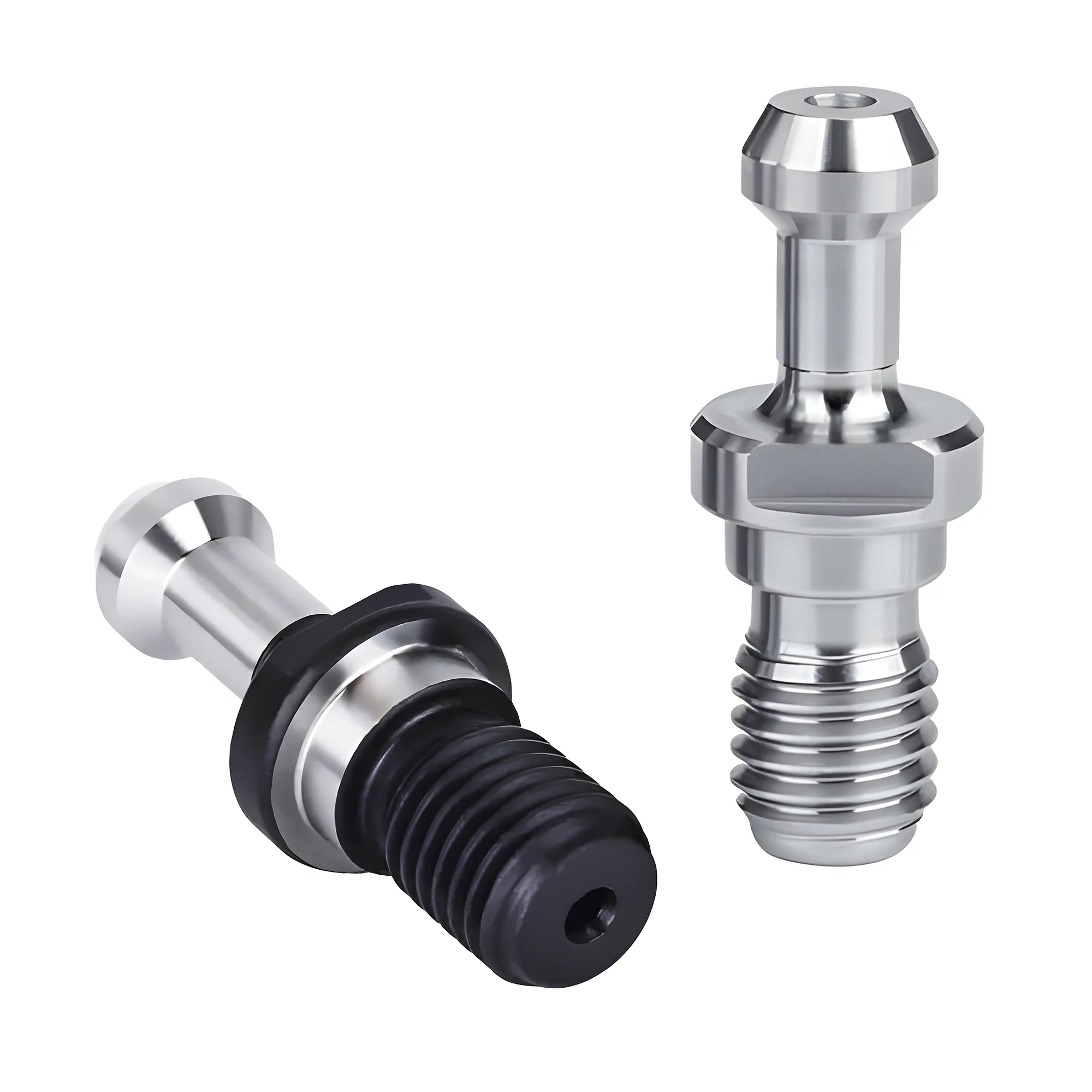
Most tool-changer jams caused by tooling trace to five spec mismatches: V-groove or flange geometry out of spec or worn, orientation key slots that miss the spindle drive keys, assemblies over the magazine's weight or moment limit (typically ~3-8 kg per tool on 40-taper vertical machining centers), the wrong pull stud form for the drawbar, and mixed holder families that share the 44.45 mm size-40 gauge diameter but differ at the flange. Diagnose with a swap test first: a holder that misbehaves in every pocket is a holder problem, while a pocket or gripper that misbehaves with every holder is a machine problem.
An automatic tool changer is unforgiving of dimensional drift because it has no operator feel: the gripper closes on the flange V-groove at a programmed height, the arm swings on a fixed timing cam, and the drawbar fingers latch the pull stud at a fixed axial position. Any holder feature that has worn, or that was never made to the right specification, turns into an alarm, a rattle, or — worst case — a dropped tool. This guide catalogs the tooling-side failure modes, gives a diagnosis flow for separating holder wear from machine wear, and shows what to measure with calipers before a third-party holder ever rides the carousel.
Quick ATC Jam Diagnosis Reference
| Problem / Goal | Primary Action | Expected Impact |
|---|---|---|
| One specific holder rattles or drops in the gripper | Caliper its flange diameter and V-groove width against a known-good holder of the same family | Isolates holder-side wear or a wrong-family body — BT40 (63 mm) and CAT40 (63.5 mm) flanges differ by only 0.5 mm yet seat differently in grippers |
| Every holder alarms at one pocket or gripper | Inspect that station's gripper fingers, pocket keys, and arm timing — machine side | A swap test isolates machine vs holder in roughly 10 minutes, before any tooling is replaced |
| Arm faults on long, heavy assemblies | Weigh the assembly and check the builder's per-tool weight AND moment limit in the manual | Keeps assemblies inside the typical ~3-8 kg envelope for 40-taper magazines; moment violations explain faults that pass the weight check |
| Intermittent clamp alarms or ejection after a pull stud change | Re-order studs by the spindle OEM's published part number, not by a generic "BT40" label | Removes the most common drawbar-grip failure — a generic stud can sit a typical ~2-4 mm off the drawbar's intended grip zone |
| Oversize cutter contacts neighboring tools in the magazine | Flag the tool as large in the tool table and assign empty adjacent pockets | Raises usable cutter diameter from roughly 75-90 mm (all pockets full) to roughly 125-150 mm on typical 40-taper magazines |
Why Tooling Spec Mismatch Jams the ATC
An automatic tool changer references four separate holder features — the flange V-groove, the orientation key slots, the pull stud, and the assembly's mass and balance — and a mismatch at any one of them produces its own characteristic jam signature. The magazine pocket holds the holder by the flange; the arm gripper carries it by the V-groove; the spindle drive keys index it by the key slots; and the drawbar clamps it by the pull stud. Because each station touches a different surface, the symptom usually names the suspect: gripper rattle points at the V-groove, a clunk at spindle insertion points at the key slots, a clamp alarm points at the pull stud, and an arm overload fault points at weight or moment.
The diagnosis flow starts with one question: is the fault following the holder or staying at the station? Run the suspect holder through several pockets and tool changes, then run known-good holders through the suspect pocket. One holder failing everywhere is a holder problem; every holder failing at one station is a machine problem. This swap test typically takes under 10 minutes and prevents the two most expensive wrong turns — re-buying tooling to fix a worn gripper, or rebuilding a gripper to fix one out-of-spec holder.
The dimensional references behind the diagnosis are the holder standards. JIS B6339 defines the BT holder's taper and flange geometry, and ANSI/ASME B5.50 fills the same role for CAT holders, so these two standards are the dimensional baseline for deciding whether a suspect holder is worn or was simply never in spec. For how the taper families compare as systems, see the BT vs CAT vs HSK comparison.
V-Groove and Flange Geometry: Out of Spec or Worn
The arm gripper carries the entire tool assembly by the V-groove machined into the flange circumference, so groove geometry errors translate directly into carry errors. Wear arrives in three forms: burrs and dings on the flange OD from drops and crashes, fretting and polishing inside the V-groove where the fingers grip, and — on third-party bodies — grooves cut at the wrong width, depth, or axial position from the start.
A holder whose V-groove geometry has drifted from the JIS B6339 or ANSI/ASME B5.50 flange callouts sits at the wrong height or angle in the gripper, and the failure is typically intermittent — the holder carries fine at slow speed but rattles or slips during rapid arm motion. Intermittency is the tell: a holder that alarms one change in five is usually a marginal-geometry holder, not a broken machine.
The reference dimensions are caliper-checkable. Manufacturer reference tables per JIS B6339 list the BT40 flange diameter at 63 mm with a 44.45 mm gauge diameter, while ANSI/ASME B5.50-based catalog data lists the CAT40 flange at 2.500 in (63.5 mm) on the same 44.45 mm gauge. BT40 and CAT40 flanges differ by only 0.5 mm in diameter, which is invisible to the eye but enough to change how gripper fingers seat in the V-groove — measure, don't eyeball. Compare the suspect holder's flange diameter, V-groove width, and groove axial position side by side against a known-good holder of the same family; a feeler-gauge-visible difference at the groove is grounds to retire the holder from ATC service.
A Dropped Holder Is a Retired Holder
A holder that has been dropped on its flange or crashed in the spindle can carry an invisible raised burr on the flange OD or groove edge. The burr re-points the gripper fingers every change and accelerates finger wear. Stone the burr lightly and re-check the groove against a known-good holder — if the groove itself is deformed, retire the holder from automatic changing rather than risking a mid-transfer drop.
Orientation Key Slot Misalignment
The two slots milled into the flange engage the spindle's drive keys, indexing the holder rotationally so the spindle can transmit torque and the ATC can return the tool at a repeatable orientation. Manufacturer reference data per JIS B6339 lists the BT40 drive slot width at 22.6 mm (16.3 mm on BT30, 35.4 mm on BT50); CAT and SK families use their own slot dimensions, which is one more reason wrong-family holders hang up at the spindle nose.
Three distinct faults converge on the same symptom — a clunk or hang as the arm presents the holder to the spindle:
- Spindle orientation drift: the spindle's programmed orientation position (the M19 stop) has drifted, so the keys no longer center in the slots. Machine-side; every holder clunks equally.
- Worn or loose drive keys: keys with rounded edges still drive torque but locate sloppily. Machine-side; look for polished wear on the key flanks.
- Slot burrs or wrong slot width: a burred or mis-machined slot on one holder catches the keys. Holder-side; the swap test isolates it.
If every holder lands with the same clunk, suspect spindle orientation or drive key wear; if one holder hangs while others land cleanly, caliper that holder's slot width against the reference dimension and inspect the slot edges for burrs. Slot edges peen over in crashes, and a peened edge a few tenths of a millimeter proud is enough to hang the holder on the key during the arm's insertion stroke.
Weight and Moment Limits: Long, Heavy Assemblies
Every magazine and arm is rated for a maximum tool weight, and the rating is lower than most operators assume. Typical 40-taper vertical machining center magazines are rated by their builders at roughly 3-8 kg per tool, and many builders publish a second limit — a moment limit — because a long assembly with its center of gravity far from the gauge line loads the arm harder than a compact assembly of the same mass. The arm accelerates the tool through its swing on a fixed cam profile; torque at the gripper scales with both mass and the distance of the center of gravity from the grip plane, so a 6 kg extended boring assembly can fault an arm that swings a 6 kg compact face mill without complaint.
Symptoms of weight or moment violations cluster at the arm: overload alarms mid-swap, audible gripper slip during the swing, tools arriving at the spindle slightly mis-oriented, and accelerated gripper finger wear concentrated on the heavy tools' pockets. Three mitigations, in order of preference:
- Check both published limits — weight and moment — in the machine manual before building a long assembly, and weigh the complete assembly (holder + tool + pull stud) rather than estimating.
- Use the control's heavy-tool option where available: many controls offer a per-tool flag or parameter that slows the arm's swing for designated pockets, trading a few seconds of change time for reliable transfer.
- Shorten and lighten the assembly — a heavier-walled but shorter arbor or a closer-coupled holder often brings the moment back inside the rating even when mass stays the same.
For very heavy or very long tools that exceed the published limits even with a slowed arm, manual loading into the spindle remains the safe path; magazines are not rated for what the spindle taper itself can carry. Imbalance compounds the problem at the spindle end — balance-grade selection for assembled holders is covered in the tool holder balance grade guide in this series.
Pull Stud Form: The Drawbar's Side of the Jam
The drawbar grips the holder by the pull stud's retention groove, and the stud is governed by a different standard than the holder body. MAS 403 governs the BT pull stud while JIS B6339 governs the BT holder body, so a BT spindle is only fully specified when both the holder standard and the pull-stud sub-type are matched. CAT studs follow the ANSI/ASME B5.50 supplement with inch threads (5/8"-11 UNC on CAT40), and SK holders take DIN 69872 / ISO 7388-2 studs (M16 on SK40) whose retention-groove geometry differs from MAS 403 even where the thread matches — ISO 7388-2 is the international standard for the retention knob (pull stud), distinct from ISO 7388-1, which governs the holder shank.
In ATC terms, a wrong-length or wrong-head-form stud presents the retention groove at the wrong axial position, so the drawbar fingers latch the wrong portion of the stud body — clamping feels normal at the tool change, but clamp-confirmation alarms appear intermittently and the tool can release under cutting load. A generic stud can sit a typical ~2-4 mm off the drawbar's intended grip zone while threading in cleanly. The identification details — thread, head face angle, length, and groove geometry across BT, CAT, Mazak, and DIN 69872 — are the ground of the pull stud compatibility guide in this series; the ATC-relevant rule is short: after any pull stud change, treat new clamp alarms or tool-change retries as a stud-spec problem first, and re-order studs by the spindle OEM's published part number rather than by taper size.
Gripper Finger Wear or Holder Wear — Which Is It?
Gripper fingers and holder V-grooves wear against each other, so late-stage symptoms look identical from the operator's side: rattle in transfer, tools seated slightly off, occasional re-grip retries. Separating them is a two-step read:
- Run the swap matrix. One holder misbehaving at every station indicts the holder; several holders misbehaving at one gripper or pocket indict that station. Log which tool numbers alarm and where — the pattern usually resolves within a shift.
- Read the contact. Stripe the suspect holder's V-groove with layout marker (or engineer's bluing), run 2-3 tool changes, and look at where the stripe is wiped. Gripper fingers in good condition wipe a symmetric, even band in the V-groove; a one-sided or patchy wipe pattern points to worn fingers, a bent finger spring, or a holder groove that no longer matches the finger profile.
Machine-side confirmation: inspect the fingers themselves for flats, rounded edges, and unequal spring force, and compare wear between a high-traffic pocket and a rarely used one. Holder-side confirmation: caliper the groove width against a new holder of the same family. Replace gripper fingers as a set, not singly — a new finger paired with a worn one grips off-center and re-creates the original symptom within weeks under typical production tool-change volumes.
Mixed BT and SK Holders in One Carousel
SK (DIN 69871), BT (JIS B6339), and CAT (ANSI/ASME B5.50) size-40 holders all gauge 44.45 mm on the same nominal 7:24 taper, which is why a wrong-family holder seats in the spindle bore while failing everywhere else in the tool-change chain. DIN 69871 places the SK V-groove at a different axial position relative to the gauge line than JIS B6339 places the BT groove, and the BT flange is noticeably thicker than SK or CAT at the same size — so grippers and pockets machined for one family mis-carry the other even though every holder "fits" the spindle.
In a mixed carousel the symptoms are distinctive: wrong-family holders sit proud of (or sink below) their neighbors in the pockets, the gripper grabs the V-groove at the wrong height and carries the holder loosely, and tool-change alarms concentrate on specific tool numbers — the imported ones. Used-tooling lots are the usual entry path, since "40-taper holders" in a job-lot listing routinely mixes SK40, BT40, and CAT40 bodies that look alike in photographs.
Sort Before Loading, Not After Alarming
Sort every mixed or used tooling lot by flange stamp first ("BT40 MAS403", "DIN 69871 AD", "CAT40"), then by pull stud thread — M16 metric narrows a size-40 holder to BT or SK, while 5/8"-11 UNC means CAT. A side-by-side flange comparison against a known holder settles the rest in under 1 minute per holder, which is cheap insurance against one dropped assembly in transfer.
Adjacent-Pocket Rules for Oversize Tools
Magazine pocket spacing fixes the largest cutter diameter that can live next to occupied pockets. On typical 40-taper magazines, the maximum tool diameter with all adjacent pockets full is roughly 75-90 mm, rising to roughly 125-150 mm when the neighboring pockets are left empty — the exact pair of values is in the machine manual's ATC specification table. Exceeding the full-pocket diameter does not alarm; it silently lets a face mill's inserts kiss the neighboring holders during indexing, machining witness marks into flanges and eventually chipping inserts.
Two rules keep oversize cutters safe:
- Declare the tool as large in the tool table. Controls with a large-tool flag reserve the adjacent pockets automatically and, on random-access magazines, prevent the pot-shuffling logic from assigning a neighbor later in the shift.
- On fixed-pocket magazines, physically leave the neighbors empty and document it at the setup sheet level, because nothing in the control enforces it. A new operator filling the "free" pockets is a classic second-shift crash.
Random-access magazines deserve special caution: the control reassigns pockets as tools return, so an oversize tool that was loaded safely can be returned next to a tall neighbor unless it is flagged. Verify the large-tool flag after every tool-table edit on random-access machines — the flag, not the original pocket choice, is what protects the clearance.
Verifying a Third-Party Holder Before You Buy the Fleet
Catalog listings cite JIS B6339 or ANSI/ASME B5.50, but the caliper confirms the body. Before committing to a fleet of third-party holders, measure one sample against the published reference dimensions and against a known-good OEM holder:
Two qualifications keep this honest. First, calipers resolve 0.01 mm at best in practiced hands, so these checks are a screen for wrong-family bodies, gross machining errors, and crash damage — not a substitute for the standards' tolerance tables, which specify limits tighter than caliper resolution on the taper itself. Second, the standards define geometry only: surface hardness, balance grade, and runout are manufacturer choices layered on top, so a dimensionally correct holder can still be a poor one. A 5-minute caliper check of gauge diameter, flange diameter, slot width, and stud thread on the first delivered holder catches the mismatches that cause ATC jams; taper contact quality and runout still need a presetter or spindle check before production. For holder-type selection beyond the interface itself, see the tool holding complete guide, and for first-machine setup context, the CNC tooling setup beginner guide.
Summary
Swap-test first, then caliper the flange — most ATC jams are a 0.5 mm story.
Separate machine wear from holder wear with a swap test before replacing anything: one holder failing everywhere is a holder problem, every holder failing at one station is a machine problem. Then measure — gauge diameter (44.45 mm at size 40), flange diameter (63 mm BT40 vs 63.5 mm CAT40), drive slot width (22.6 mm BT40), and pull stud thread — against JIS B6339 / ANSI/ASME B5.50 reference data and a known-good holder. Keep assemblies inside the builder's weight and moment limits (typically ~3-8 kg per tool on 40-taper magazines), never mix BT and SK bodies in one carousel, flag oversize cutters for empty adjacent pockets, and order pull studs by the spindle OEM's part number.
Why does my ATC drop or rattle only one specific tool holder?
That pattern points at the holder, not the machine. Caliper its flange diameter and V-groove width against a known-good holder of the same family — BT40 flanges measure 63 mm and CAT40 63.5 mm, and wear or a wrong-family body changes how the gripper fingers seat. Burrs or fretting in the V-groove produce the same symptom.
How much weight can a CNC tool changer handle per tool?
Typical 40-taper vertical machining center magazines are rated by builders at roughly 3-8 kg per tool, while 50-taper machines are commonly rated in the ~12-25 kg per-tool range — but the exact figure is always the builder's published spec, not a taper-size rule. Many builders also publish a moment limit, so a long assembly with its center of gravity far from the gauge line can fault the arm even under the weight limit. Check the machine manual for both values.
Can I mix BT40 and SK40 holders in one tool carousel?
Not reliably. Both gauge 44.45 mm on the same 7:24 taper and seat in the spindle bore, but flange thickness, V-groove position, and gripper groove geometry differ between JIS B6339 and DIN 69871, so grippers and pockets machined for one family mis-carry the other. Sort mixed cribs by flange stamp and pull stud thread before loading a magazine.
How do I verify a third-party BT40 holder before buying in quantity?
Caliper one sample against published reference dimensions — 44.45 mm gauge diameter, 63 mm flange diameter, 22.6 mm drive slot width, and an M16 pull stud thread per JIS B6339 / MAS 403 reference data. Then compare V-groove width and axial position side by side with a known-good OEM holder; catalogs cite the standard, but the caliper confirms the body.
How do I tell gripper finger wear from tool holder wear?
Run a swap test: several holders misbehaving at one gripper or pocket indicts the machine side, while one holder misbehaving at every station indicts the holder. A marker or bluing stripe in the V-groove, read after 2-3 tool changes, shows where the fingers actually contact — a one-sided or patchy wipe pattern means worn fingers.