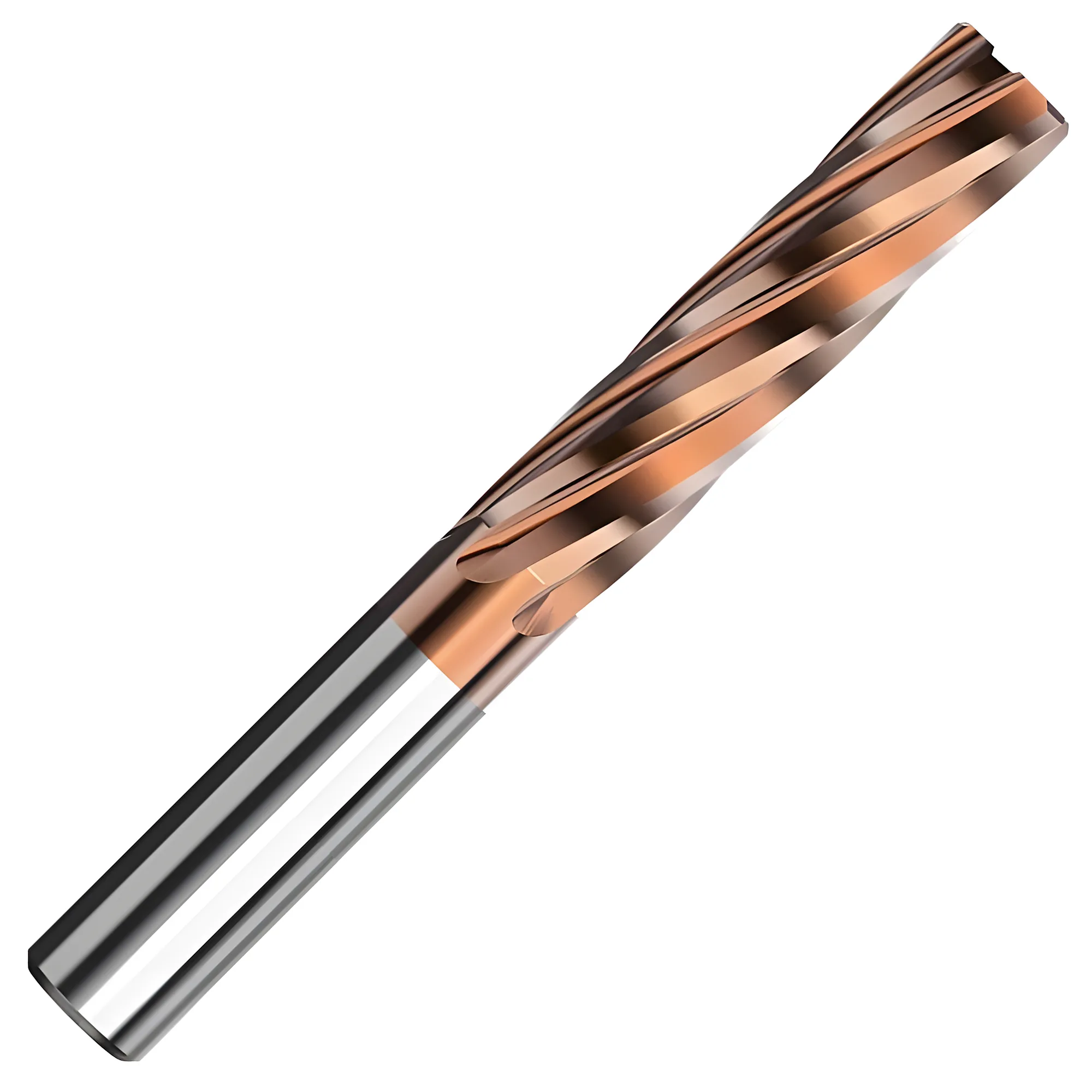
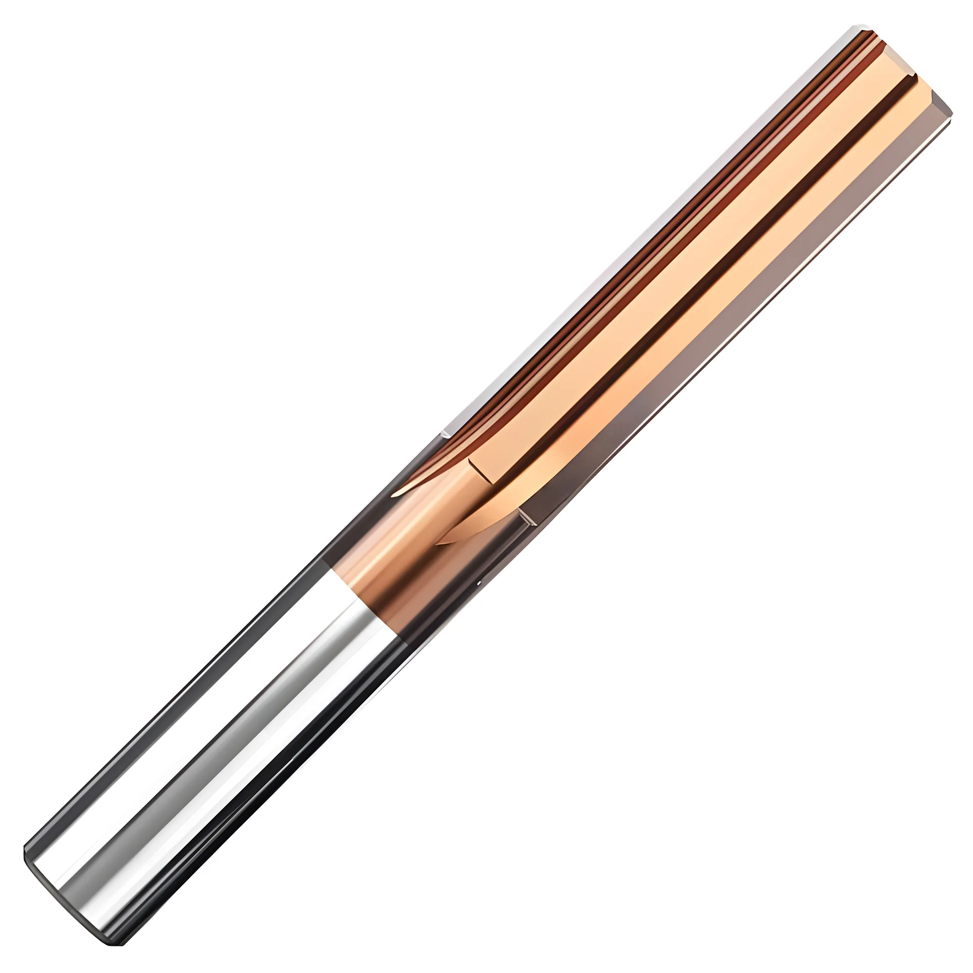
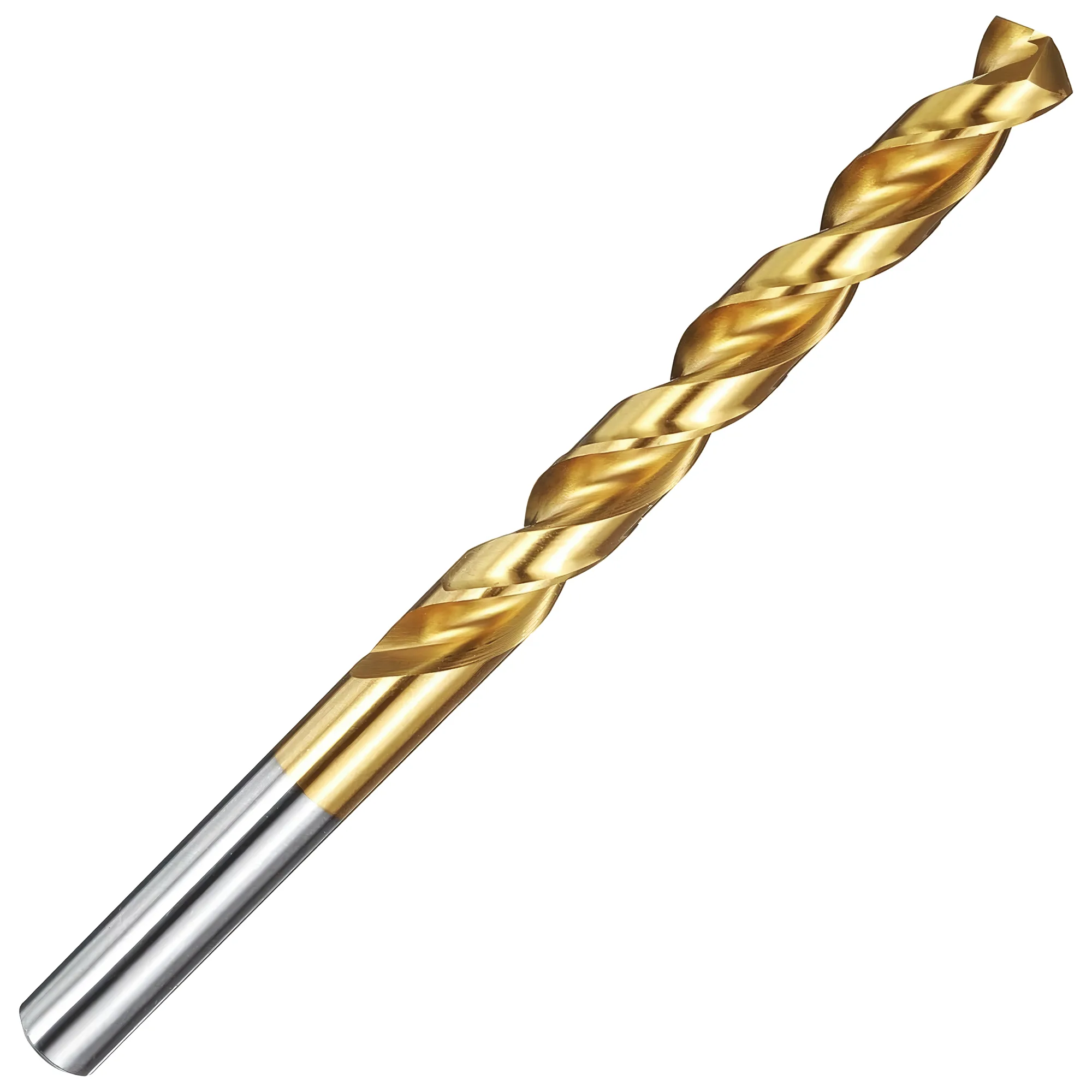
For machine reaming in steel, leave 0.15-0.25 mm stock on diameter and feed at 0.15-0.30 mm/rev to consistently achieve H7 tolerance (0 to +0.015 mm on a 10 mm hole per ISO 286-2, unilateral upward) and Ra 0.4-0.8 µm. Too little stock (under 0.05 mm) causes rubbing and glazing; too much (above 0.4 mm) overloads the chamfer and produces chatter and an oversized hole. Through-holes and blind holes require different feed and coolant strategies because chip evacuation — not cutting force — is the dominant variable once allowance is correct.
Quick Reaming Parameter Reference
| Problem / Goal | Primary Action | Expected Impact |
|---|---|---|
| Hole oversized after reaming | Reduce stock allowance to 0.10-0.15 mm on diameter | Oversize error drops from ±0.03 mm to ±0.01 mm in typical rigid setups |
| Poor surface finish (Ra above 1.6 µm) | Increase feed to 0.20-0.30 mm/rev; verify stock ≥ 0.10 mm | Ra typically improves to 0.4-0.8 µm range when chips break cleanly |
| Reamer dulls after 50 holes | Verify stock allowance < 0.30 mm; add flood coolant | Carbide reamer life typically 200-500 holes in mild steel with correct allowance |
| Chatter in through hole | Increase stock allowance from < 0.10 mm to 0.15 mm | Chatter caused by rubbing; heavier chip load damps vibration in most cases |
| Undersized hole in blind hole | Switch from flood to through-tool coolant; verify chip evacuation | Chip packing in blind holes adds 0.01-0.03 mm apparent undersize |
| H6 not achievable with reaming alone | Add honing pass or floating reamer head after reaming to H7 | Honing removes 0.005-0.015 mm and achieves Ra below 0.4 µm |
Why Stock Allowance Controls Everything
Reaming is a calibration operation, not a material-removal operation — the chamfer must engage cleanly to cut rather than rub, and the stock allowance window that allows this is narrower than most machinists expect.
A machine reamer (DIN 212 / ISO 521) removes stock only on its 45° lead chamfer. The body flutes behind the chamfer are calibration lands that burnish the bore to size — they do not cut. When the allowance is correct:
- Each cutting edge on the chamfer encounters a predictable chip thickness
- Chips break and evacuate before reaching the calibration lands
- The bore wall is progressively finished by the burnishing land to a predictable Ra
When allowance is too small (under 0.05 mm on diameter), the chamfer does not engage enough workpiece material to form a proper chip. Instead, the cutting edge ploughs a thin smear layer, work-hardening the surface and producing a glazed bore that resists measurement and wears the reamer rapidly.
When allowance is too large (above 0.40 mm on diameter), the chamfer is overloaded. The cutting force on each flute exceeds the reamer's bending stiffness, causing the tool to deflect off-center and produce an oversized hole — typically 0.02-0.05 mm larger than nominal in HSS reamers and 0.01-0.03 mm in solid carbide versions.
The production-safe stock allowance window for machine reaming steel is typically 0.10-0.30 mm on diameter, with 0.15-0.25 mm as the reliable center-of-process target for H7 work.
Feed Rate — Counter-Intuitive Rules for Reamers
Reamers improve surface finish at heavier feed, not lighter — this is the opposite of turning and drilling, where reducing feed always reduces Ra.
The reason is in the chip-formation mechanism. A reamer's calibration land trails each cutting edge by 0.1-0.3 mm. If feed is too light (under 0.08 mm/rev), the chip is too thin to break cleanly from the cutting edge. Instead, it smears across the calibration land as a thin metallic film, scratching the bore in the direction of rotation. The visual result is a cross-hatched scoring pattern with Ra values typically 1.5-3.0 µm.
At heavier feed (typically 0.15-0.30 mm/rev), each flute takes a thicker bite that breaks as a discrete chip. The calibration land then contacts a clean bore wall and burnishes it to the target Ra.
The surface finish formula for turning is Ra = f² / (32 × r), where f is feed per revolution and r is tool nose radius. For a deeper treatment of Ra and surface texture parameters, see surface finish specification and measurement. Feed dominates surface finish because it appears squared — halving feed in turning reduces Ra by 75%. For reaming, this geometric relationship breaks down below the minimum chip-thickness threshold because the reamer stops cutting and starts rubbing. The practical implication: always confirm that feed in mm/rev is above the chip-thickness floor for the material, not just that it produces low theoretical Ra.
| Material | Recommended Feed/rev | Minimum Chip-Forming Feed | Note |
|---|---|---|---|
| Mild steel (≤30 HRC) | 0.15-0.30 mm | 0.10 mm | Below 0.10 mm: smearing and glazing |
| Stainless steel (austenitic) | 0.10-0.25 mm | 0.08 mm | Work-hardens; dwell worsens finish |
| Aluminum / copper alloys | 0.20-0.40 mm | 0.15 mm | High feed prevents BUE on soft alloys |
| Cast iron (grey) | 0.15-0.30 mm | 0.10 mm | Granular chips; feed controls Ra directly |
| Brass / bronze | 0.15-0.35 mm | 0.10 mm | Low feed causes skiving rather than cutting |
Best Practice: Set Feed First, Then Speed
When setting up a new reaming operation, establish the feed rate before cutting speed. Set feed to 0.20 mm/rev as a starting point, check the chip (it should be a short, curled ribbon, not a smear), then adjust speed to control heat and surface finish. Reversing the sequence leads machinists to reduce feed when finish is poor — usually the wrong direction.
Cutting Speed — The Heat-and-Size Trade-off
Cutting speed in reaming controls thermal expansion, bore size, and tool life — but has less direct influence on Ra than feed and stock allowance.
The standard recommendation for carbide reamers is 50-70% of the cutting speed used for drilling the same diameter in the same material. For mild steel, this typically means 60-100 m/min for solid carbide versus 80-120 m/min for drilling. For HSS reamers, use 30-50% of HSS drilling speed.
The reason for the speed reduction is thermal management:
- Bore diameter thermal expansion — at elevated cutting temperatures, the workpiece bore expands during cutting and contracts after the reamer exits. In production reaming of steel at correct allowance, running above 120 m/min in carbide commonly produces holes that measure 0.010-0.020 mm oversize after cooling compared to the measurement taken while the part is still warm from machining.
- Calibration land rubbing heat — unlike a turning insert, a reamer's calibration land continuously contacts the bore wall over the full reaming depth. Higher speed increases the rubbing heat, which smears soft material back onto the land and builds up a micro-edge that scores the surface.
- Chip color as a speed indicator — correct speed produces silver-grey chips in steel. Straw-colored (light temper) chips indicate the upper end of acceptable speed. Blue chips indicate overheating; reduce speed by 20% and increase flood coolant flow.
At correct feed and allowance, solid carbide reamers with AlTiN+TiSiN coating typically achieve 200-500 holes per tool in mild steel before Ra exceeds 0.8 µm, compared to 50-150 holes for HSS reamers under the same conditions.
Avoid Dwell in the Cut
Avoid dwelling (pause spindle rotation while reamer is engaged) during a reaming pass in ductile materials (steel, stainless, aluminum). Even a 1-second spindle pause with the reamer stationary in the bore causes the cutting edges to mark the bore at the dwell position — typically producing a Ra spike of 1.5-3.0 µm at a single angular location in materials prone to adhesion. This is particularly damaging in stainless steel and aluminum where material transfer to the cutting edge occurs quickly. If a machine stop is unavoidable, retract the reamer completely before stopping the spindle.
Through-Holes vs Blind Holes — Different Strategies
The critical difference between through-hole and blind-hole reaming is not cutting geometry but chip management — the same allowance and feed that produces H7, Ra 0.6 µm in a through hole will produce Ra 1.5 µm and a 0.02 mm oversize in a blind hole if chip evacuation is not addressed.
Through-Hole Strategy
Through holes allow chips to exit from either end. For through holes:
- Feed per revolution: standard range applies (0.15-0.30 mm/rev for steel)
- Coolant: flood coolant entering at the spindle side and exiting through the hole is most effective. The coolant flow carries chips ahead of the reamer exit
- Retract speed: the reamer can be retracted at rapid traverse after cutting — no finish concern on the way out because the calibration land is already sized
For through holes, a right-hand spiral flute reamer with 7-10° helix pulls chips backward toward the shank, keeping them clear of the calibration lands as the reamer advances. Straight flute reamers push chips downward through the hole exit and work well when chips can fall freely. For chip flow details by hole geometry, see the spiral flute vs straight flute reamer guide.
Blind-Hole Strategy
Blind holes require specific adjustments because chips have only one exit path — back up the hole past the reamer:
- Stock allowance: use the lower half of the material range (0.10-0.20 mm for steel) to minimize chip volume in the bottom of the bore
- Coolant: through-tool coolant at 30-50 bar is the most reliable approach for blind holes — the pressurized flow lifts chips upward and out past the reamer flutes. Flood coolant without through-tool pressure is often insufficient for holes deeper than 3× diameter
- Feed rate: reduce by 10-15% compared to through-hole recommendations for the same material. The reduction lowers chip volume and reduces the risk of chip-packing pressure at the bottom of the bore
- Chip clearance at bottom: ensure the pre-drilled hole has at least 1.5× reamer diameter of clearance beyond the target depth for chip accumulation before the reamer's chamfer reaches full depth
- Left-hand spiral flute reamer: for steel blind holes, a LH/RH reamer pushes chips away from the calibration land toward the bottom of the bore. This prevents the most common blind-hole failure mode — chips re-entering between the calibration land and the bore wall
Through-tool coolant at 30-50 bar is the most reliable method for blind-hole reaming beyond 3× diameter, typically reducing bore oversize from chip packing by 0.01-0.03 mm compared to flood-only coolant.
| Parameter | Through Hole | Blind Hole |
|---|---|---|
| Stock allowance (steel) | 0.15-0.25 mm on ø | 0.10-0.20 mm on ø |
| Feed per rev (steel) | 0.15-0.30 mm | 0.13-0.25 mm |
| Coolant type | Flood or through-tool | Through-tool at ≥30 bar |
| Reamer retract | Rapid traverse | Slow retract at feed rate (half-speed) |
| Preferred flute type | RH spiral or straight | LH/RH spiral |
| Minimum chip clearance | 0.5× ø below exit | 1.5× ø below target depth |
Achieving H6 vs H7 vs H8 — When Reaming Is Enough
ISO 286-2 defines the tolerance range for H7 on a 10 mm nominal hole as 0 to +0.015 mm (15 µm) — a correctly set-up machine reaming operation in solid carbide can reliably hold this tolerance in steel under stable conditions.
Reaming with standard machine reamers and proper allowance/feed parameters typically achieves these tolerance classes:
- H8 and coarser: achievable with HSS reamers at standard parameters. H8 on 10 mm is 22 µm range; most HSS reamers in good condition stay within half this range.
- H7: the standard target for solid carbide reamers. Requires stock allowance within the 0.10-0.25 mm range, feed at 0.15-0.25 mm/rev, and flood or through-tool coolant. Achievable in production with process Cpk above 1.3 on a rigid CNC machining center.
- H6: H6 on 10 mm is 9 µm range — at the practical limit for fixed reaming. Achievable with solid carbide, floating reamer holder (to cancel spindle runout), correct allowance, and careful thermal management. Process Cpk of 1.0-1.33 is typical; for higher Cpk, add a honing pass.
- H5 and finer: not reliably achievable with fixed reamers. Use drill-ream-hone, fine boring, or single-point boring.
ISO 286-2 is the governing standard for hole-shaft fits in metric practice — every machinist working to H7, H8, or H6 specifications is working within its tolerance tables, whether they cite it or not.
The table below gives the actual tolerance range (in µm) for common nominal diameters and tolerance classes, so the reader can evaluate whether reaming is the correct final operation for their required fit:
| Nominal Diameter | H6 Range | H7 Range | H8 Range |
|---|---|---|---|
| 3-6 mm | 8 µm | 12 µm | 18 µm |
| 6-10 mm | 9 µm | 15 µm | 22 µm |
| 10-18 mm | 11 µm | 18 µm | 27 µm |
| 18-30 mm | 13 µm | 21 µm | 33 µm |
| 30-50 mm | 16 µm | 25 µm | 39 µm |
Source: ISO 286-2 tolerance tables for fundamental deviation H (zero lower deviation).
Solid carbide reamers with AlTiN+TiSiN coating are the standard substrate for production H7 reaming of steel because the nano-composite outer layer maintains hardness under abrasive wear, extending in-tolerance tool life compared to single-layer coatings.
Troubleshooting Common Reaming Failures
Most reaming failures fall into three categories: size error (over- or undersize), finish failure (Ra above specification), or premature tool wear — and each traces back to a specific controllable parameter.
Oversize Holes
Oversize holes after reaming are typically caused by one of three factors:
- Excess stock allowance — pre-drilled hole too small forces the reamer to remove more than the chamfer geometry was designed to handle. Check the drilled diameter before reaming; a drill running with 0.02 mm runout will produce an oversize pre-hole that compounds the problem.
- Spindle runout transferring to bore — a reamer running with approximately 0.02-0.03 mm TIR runout can produce a bore 0.01-0.02 mm larger than the reamer's nominal diameter because each flute sweeps a slightly different arc. Use a hydraulic chuck or shrink-fit holder to reduce runout below 0.005 mm TIR for H7 work.
- Thermal expansion — bore measured immediately after reaming is 0.005-0.015 mm larger than the same bore measured after cooling to room temperature in steel at high cutting speeds. Always measure after cooling for final inspection.
Undersized Holes
Undersized holes in through holes are uncommon (the reamer is the size reference) but occur in blind holes due to chip packing. Chips accumulate at the bottom of the bore, increasing resistance and lifting the reamer slightly off the fully-advanced position. Through-tool coolant at 30-50 bar and a reduced allowance (lower half of the material range) are the two most effective corrective actions for blind-hole undersizing caused by chip packing.
Poor Surface Finish
Ra above specification after reaming traces to:
- Feed too light — smearing instead of cutting (see Section 02). Increase feed first.
- Stock allowance below 0.10 mm on diameter — reamer is rubbing, not cutting. Reduce pre-drill size.
- Worn calibration land — once the calibration land wears to a radius narrower than 0.05 mm, it loses its burnishing action and Ra rises sharply. Inspect under 10× magnification; replace or recondition.
- Coolant interruption — a momentary coolant dropoff during the reaming pass leaves a dry-cut mark at the interruption point. Ensure coolant flow is confirmed before spindle start.
Stock Allowance Is Not Optional to Adjust
Increasing stock allowance to "be safe" is counterproductive. Leaving 0.40-0.50 mm on diameter in an attempt to guarantee material removal typically overloads the chamfer, increases bore oversize to 0.03-0.05 mm, and causes premature reamer failure in the first 20-50 holes. Use the correct allowance for the material and diameter.
Integrated Parameter Setup Workflow
The following sequence sets reamer allowance, feed, and speed in a production-proven order that catches errors before the first hole is cut. For choosing between spiral flute and straight flute reamer types before this setup, see the drill bit and reamer selection guide.
- Confirm reamer nominal diameter and tolerance class — check the reamer body marking. Standard reamers are ground to H7 tolerance (0 to -0.010 mm on body diameter for most sizes). If the reamer is slightly undersize from previous use, adjust target allowance to compensate.
- Calculate target pre-drill diameter — target pre-drill = reamer nominal − allowance. For a 12H7 reamer targeting 0.20 mm allowance: pre-drill to 11.80 mm. Pre-drill oversized and the reamer cannot hold H7; pre-drill undersized and the reamer overloads.
- Set feed rate — enter 0.20 mm/rev as the starting point for steel. Do not reduce below 0.15 mm/rev in an attempt to improve finish (see Section 02).
- Set cutting speed — start at 70 m/min for solid carbide reaming steel. If chips emerge straw-colored (light temper), the speed is at the upper limit; reduce by 10-15% for production consistency.
- Verify coolant flow before starting — for through holes: confirm flood coolant is flowing from the spindle side. For blind holes: confirm through-tool coolant at ≥30 bar before spindle start.
- Cut one hole, measure, adjust — measure bore diameter after cooling. If oversize by 0.01-0.03 mm, increase pre-drill diameter by 0.05 mm (reduce allowance). If Ra is above 0.8 µm, increase feed by 0.05 mm/rev or verify coolant flow.
Establishing the correct pre-drill diameter is the single most impactful setup step because allowance errors compound all other parameter effects — a 0.05 mm allowance error can typically produce a 0.02-0.03 mm size error that no feed or speed adjustment can fully correct.
Set allowance to 0.15-0.25 mm on diameter, feed to 0.15-0.30 mm/rev, and speed to 50-70% of drilling speed.
Correct stock allowance is the foundation of all reaming quality. Keep pre-drill diameter 0.15-0.25 mm below reamer nominal for steel (0.10-0.20 mm for stainless and blind holes). Feed above the chip-forming minimum — 0.15 mm/rev in steel — so the reamer cuts rather than rubs. For blind holes, use through-tool coolant at 30-50 bar and reduce allowance to the lower half of the material range to control chip packing. Solid carbide reamers with AlTiN+TiSiN coating in these conditions typically achieve H7 tolerance and Ra 0.4-0.8 µm for 200-500 holes before reconditioning.
What stock allowance should I leave for machine reaming in mild steel?
Leave 0.15-0.25 mm on diameter as the production center-of-process target for mild steel up to 30 HRC. Below 0.10 mm, the reamer rubs rather than cuts, glazing the bore and wearing the calibration land rapidly. Above 0.30 mm, chamfer overload commonly produces holes 0.02-0.05 mm oversize. Larger diameter reamers (above 20 mm) can use the upper end of the range; reamers under 10 mm should use the lower end.
Why does heavier feed improve surface finish when reaming?
At light feed (below 0.10 mm/rev in steel), chip thickness falls below the minimum needed for clean chip formation. The cutting edge smears a thin layer across the calibration land instead of producing a discrete chip, resulting in a scored bore with Ra typically 1.5-3.0 µm. At 0.20-0.30 mm/rev, chips break cleanly before contacting the calibration land, and the land burnishes the bore to Ra 0.4-0.8 µm. This is the opposite of turning, where lower feed always reduces Ra.
How do I ream a blind hole to H7 tolerance without chip packing?
Use a left-hand spiral, right-hand cut reamer to push chips away from the calibration land, reduce stock allowance to 0.10-0.20 mm on diameter (lower half of the steel range), and supply through-tool coolant at 30-50 bar minimum. Chip packing at the blind-hole bottom typically adds 0.01-0.03 mm of apparent undersize and raises Ra above specification. Retract the reamer at half-feed rate rather than rapid traverse to avoid dragging chips back across the bore wall.
What cutting speed should I use for solid carbide reamers in steel?
Start at 60-100 m/min for solid carbide reamers in mild steel — approximately 50-70% of the cutting speed you would use for drilling the same diameter. Running faster than 120 m/min in steel commonly produces holes that measure 0.010-0.020 mm oversize after cooling due to thermal expansion during the cut. Monitor chip color: silver-grey is correct; straw-colored indicates the upper speed limit; blue chips require a 20% speed reduction.
When should I use honing instead of reaming for tight tolerances?
Use honing when H6 tolerance (9 µm range on a 10 mm hole per ISO 286-2) or better is required at a process Cpk above 1.33, or when Ra below 0.4 µm is specified. Fixed reaming in solid carbide can hold H7 (15 µm) reliably and approach H6 (9 µm) with floating holders, but the process capability decreases sharply below H6. A drill-ream-hone sequence removes 0.005-0.015 mm in the honing step and achieves Ra 0.1-0.4 µm on bore finishes that reaming alone cannot consistently reach.
Sources
- ISO 286-2 — Limits and Fits: Tables of Standard Tolerance Grades and Limit Deviations for Holes and Shafts
- DIN 212 — Machine Reamers with Cylindrical Shank
- ISO 521 — Machine Reamers with Morse Taper Shanks
- ISO 4287 — Surface Texture: Profile Method, Terms, Definitions and Surface Texture Parameters
- Machinery's Handbook, 32nd Edition — Reaming Operations and Feeds and Speeds
- Sandvik Coromant — Reaming: Process Parameters and Troubleshooting