CNC cutting tools fall into three broad groups: solid tools (end mills, drills, taps), indexable tools (turning inserts, face mills, boring bars), and specialized tools (thread mills, grooving tools). Coatings (CVD 8-20 µm, PVD 1-8 µm) apply across all groups. Selecting the right tool-coating-grade combination for each operation can improve tool life by 2-5x and reduce cost per part by 20-50% under optimized conditions. This guide covers every major category with ISO-based selection criteria and parameter recommendations.
Cutting tools span a wide range of geometries and materials, from solid carbide end mills to indexable face mills to single-point boring bars. Each category has its own selection criteria, but they all share a common truth: performance depends on matching the tool to the workpiece material, the operation type, and the machine's capability. What follows is a comprehensive walkthrough of each tool family, the engineering principles behind them, and practical decision rules grounded in ISO standards and shop-floor experience.
End Mills — Flute Count, Geometry, and Material
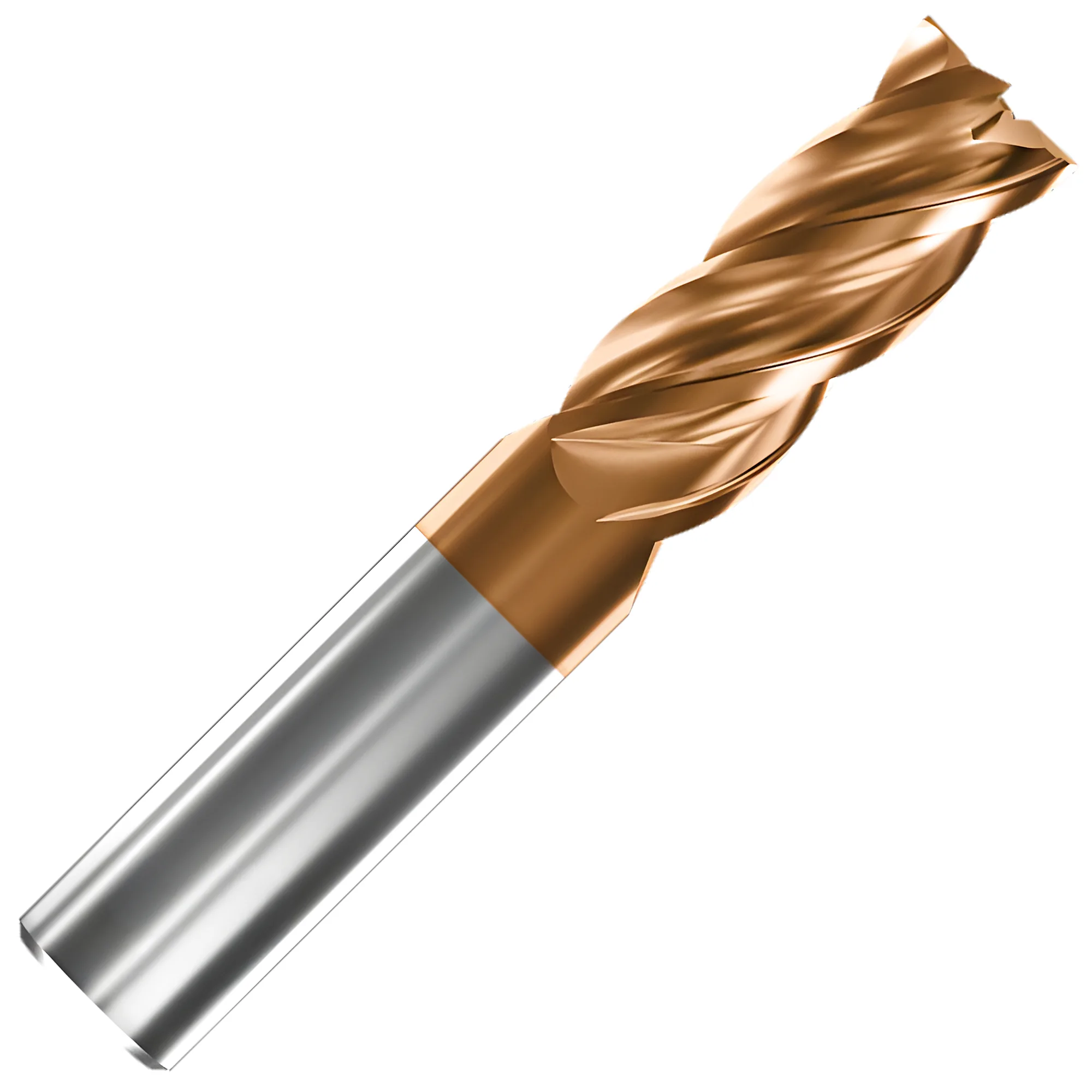
End mills are the most versatile tools in any CNC milling operation, handling everything from roughing to finishing, slotting to profiling. The three primary selection variables are flute count, substrate material, and helix angle. For general-purpose end mill selection, 2-3 flutes are typically chosen for aluminum to clear long stringy chips, while 4-6 flutes are typically chosen for steel and stainless to enable higher table feed rates.
Flute count determines the balance between chip evacuation and feed rate. Fewer flutes create larger chip valleys for materials like aluminum that produce long, stringy chips. More flutes allow higher feed rates in steel and hardened materials where chips are small and discontinuous.
| Flute Count | Chip Space | Primary Materials | Typical Use |
|---|---|---|---|
| 2 flutes | Maximum | Aluminum, plastics, composites | Slotting, deep pocketing |
| 3 flutes | Large | Aluminum at higher MRR, soft alloys | General aluminum milling |
| 4 flutes | Moderate | Carbon steel, alloy steel, stainless (roughing) | General-purpose steel milling |
| 5-6 flutes | Minimal | Hardened steel (>45 HRC), finishing passes in stainless | Finishing, high-feed at light DOC |
Increasing flute count allows higher table feed rates in principle (vf = fz × z × n), but chip evacuation limits often require reducing feed per tooth — so the relationship is not a simple linear multiplier. In practice, a 4-flute end mill in steel may run at 1.5-1.8x the table feed of a 2-flute, not 2x.
For roughing stainless steel, 4 flutes with aggressive chip loads work better — large flute valleys prevent chip packing in gummy austenitic grades.
Helix angle affects chip evacuation, surface finish, and cutting force direction. A standard 30-degree helix suits most operations. High-helix designs at 45 degrees improve finish in aluminum and reduce cutting forces. Variable-helix end mills (e.g., 35/38 degrees) break up harmonic chatter patterns and are worth considering for deep pockets or long-reach applications.
Geometry rules of thumb:
- Use the shortest length of cut (LOC) that clears your feature — deflection scales with the cube of stickout length
- A 0.5mm corner radius can increase tool life by up to 50% over a sharp corner in steel and stainless applications by distributing forces across a larger contact area
- Keep stickout under 3xD whenever possible; above 5xD in slotting or heavy engagement may require dampening measures (light radial engagement at 5-6xD is often manageable with HSM toolpaths)
For a detailed breakdown of flute count selection by material, coating interactions, and geometry optimization, see the full end mill selection guide.
Carbide Grades and Substrates — ISO Classification
ISO 513 is the universal starting point for carbide grade selection because it sorts every manufacturer's grade into one of six application groups (P, M, K, N, S, H) based on the dominant wear mechanism of the target material family. Carbide insert grades are classified under ISO 513:2004 into six application groups. This standard is the universal starting point for grade selection across all manufacturers — but it is not a grade equivalence standard. ISO 513 §4 explicitly states: "A group of application is not identical to a cutting material grade. Grades from different manufacturers which are in the same application group could be different as far as application range and performance level are concerned." A Sandvik P25 grade and a Kennametal P25 grade are not directly interchangeable in cutting performance — they share the application group, not the chemistry, geometry, or wear behavior. Use ISO 513 as a starting filter for material selection, not as a substitute for vendor data.
| ISO Group | Color Code | Target Materials | Primary Wear Mechanism |
|---|---|---|---|
| P (Steel) | Blue | Carbon steel, alloy steel, ferritic stainless | Crater wear |
| M (Stainless) | Yellow | Austenitic stainless, duplex, cast steel | Notch wear, built-up edge |
| K (Cast Iron) | Red | Gray iron, ductile iron, malleable iron | Abrasive flank wear |
| N (Non-Ferrous) | Green | Aluminum, copper, brass, plastics | Built-up edge |
| S (Superalloys) | Brown | Titanium, Inconel, cobalt alloys | Notch wear, thermal damage |
| H (Hardened) | Gray | Hardened steel >45 HRC, chilled cast iron | Crater and flank wear |
Within each group, a two-digit number indicates the hardness-toughness balance. Lower numbers (P01, P10) are harder but more brittle — suited for finishing at high speeds under stable conditions. Higher numbers (P35, P45) are tougher but wear faster — designed for heavy roughing, interrupted cuts, and unstable setups. Most general machining falls in the P20-P30 range. For a deeper walkthrough of how WC grain size and Cobalt content shift the hardness-toughness curve within an ISO group, see the carbide grade selection guide.
Substrate composition matters. Carbide inserts are sintered composites of Tungsten Carbide (WC) grains in a Cobalt (Co) binder. Finer grain sizes (submicron, <0.5 um) yield maximum hardness and edge sharpness for finishing. Higher Cobalt content (12-15%) is preferred for heavy roughing because the ductile binder absorbs impact energy that would otherwise fracture the brittle WC grains. A standard general-purpose grade typically uses fine grain (0.5-1.0 um) with 10% Cobalt.
Cross-Group Misapplication
Using a P-group grade on stainless steel or a K-group grade on aluminum will typically underperform, especially in austenitic stainless and ductile cast iron where the wear mechanisms differ most. Each ISO group is engineered to resist the specific wear mechanism dominant in that material family. P grades resist crater wear from steel. K grades resist abrasive flank wear from cast iron. Mismatching the group means the grade fights the wrong failure mode.
Tool wear measurement standards. Tool life testing follows two ISO standards depending on operation: ISO 3685:1993 for single-point turning and ISO 8688-1:1989 for face milling. Both define flank wear (VB) as the primary criterion — VB_B = 0.3 mm average (turning) or 0.35 mm uniform (face milling) for normal life. For carbide tools in turning, ISO 3685 §8.2.2 also defines a crater depth criterion: KT = 0.06 + 0.3f (where f is feed in mm/rev), giving KT = 0.14 mm at f = 0.25 mm/rev or 0.25 mm at f = 0.63 mm/rev. The reference grades are P25 for milling steel and K10 for milling cast iron per ISO 8688-1 §4.4.
Coating Technologies — CVD vs PVD
Coatings extend tool life by 3x to 10x by reducing friction, increasing surface hardness, and providing a thermal barrier at the cutting edge. The two dominant technologies — Chemical Vapor Deposition (CVD) and Physical Vapor Deposition (PVD) — produce fundamentally different coatings suited to different applications. CVD coatings are typically chosen for continuous turning above 200 m/min because the Al2O3 layer acts as a thermal barrier, while PVD coatings are typically chosen for milling and threading because compressive residual stress resists impact-driven micro-cracking.
| Property | CVD | PVD |
|---|---|---|
| Coating Thickness | 8-20 µm | 1-8 um |
| Edge Sharpness After Coating | Rounded | Sharp (preserved) |
| Thermal Barrier | Excellent (Al2O3 layer) | Moderate |
| Interrupted Cutting | Risk of cracking | Excellent |
| Adhesion | Strong chemical bond at high temp | Dense atomic deposition at lower temp |
| Cost per Insert | Lower (batch process) | Higher |
The general guideline: CVD excels in continuous, high-speed, high-temperature operations on steel and cast iron. PVD wins in interrupted cutting (milling, grooving, threading), sharp-edge applications (finishing, small inserts), and difficult materials (stainless, titanium, superalloys).
Common PVD coating types include TiN (general purpose), TiAlN (dry machining, hardened steel), AlCrN (high-temperature alloys), and DLC (aluminum, prevents built-up edge). CVD coatings typically use a multi-layer stack of TiN/MT-TiCN/Al2O3 for maximum thermal protection and wear resistance. For the side-by-side process, residual stress, and application breakdown that drives the choice between the two, see CVD vs PVD coated inserts.
Coating and Coolant Interaction
TiAlN and AlCrN coatings perform best in dry or MQL (minimum quantity lubrication) conditions. In milling, flood coolant causes thermal shock cycling that can crack these coatings. In drilling and continuous turning, flood coolant with TiAlN is standard practice. For flood coolant applications, TiN or TiCN coatings are more durable.
Face Mills and Shell Mills — When to Use Each
Face milling accounts for more material removal in CNC shops than any other single operation. The choice between face mills and shell mills comes down to cutter geometry, mounting method, and application requirements. A 45-degree lead-angle face mill is typically preferred for large flat surfaces with demanding finish requirements because it directs forces axially into the spindle and thins each chip to 71% of programmed feed. Shell mills mount onto a separate arbor per ISO 6462, which standardizes the central bore-and-keyway interface so one arbor can accept multiple cutter body diameters.
Face mills mount directly to the spindle via an integral arbor or adapter. They carry inserts primarily on the face (bottom) of the cutter body and are available in diameters from 50mm to 315mm. The lead angle — typically 45 or 90 degrees — determines how cutting forces are distributed between axial and radial directions.
Shell mills mount onto a separate arbor via a central bore and keyway. The key advantage is modularity: one arbor accepts multiple cutter body diameters. Shell mills typically range from 40mm to 160mm diameter.
| Factor | 45° Face Mill | 90° Face/Shell Mill | Shell Mill (modular) |
|---|---|---|---|
| Primary Force Direction | Axial (into spindle) | Radial (into workpiece) | Depends on geometry |
| Chip Thinning | Yes (71% of programmed feed) | No | Depends on geometry |
| Max Depth of Cut | 4-8mm | 10-15mm | Varies by insert |
| Shoulder Milling | No | Yes | Yes |
| Surface Finish (with wiper) | Ra 0.4-0.8 um | Ra 2.4-4.8 um | Ra 1.6-3.2 um |
Chip Thinning Compensation
A 45-degree lead angle reduces actual chip thickness to 71% of programmed feed per tooth. To maintain the correct material removal rate, increase feed per tooth by 1.4x. Under-feeding accelerates flank wear from rubbing rather than cutting.
Choose a 45-degree face mill for large flat surfaces with demanding finish requirements. Choose a 90-degree cutter when shoulder milling or full-depth axial cutting is needed. Choose a shell mill when budget requires sharing arbors across multiple cutter body diameters. The detailed comparison with insert economy analysis is covered in face mill vs shell mill.
Thread Milling vs Tapping
Internal thread production on CNC machines involves a fundamental tradeoff: tapping is generally faster for standard sizes but less flexible, while thread milling is more versatile and safer in difficult materials. For large threads (M30+), thread milling can be competitive or faster since large taps require high torque and are expensive. Thread milling is typically preferred for hardened steel above 35 HRC and for blind holes in stainless or titanium because the cutter is always smaller than the bore, eliminating the trapped-chip failure mode that breaks taps.
Tapping uses a form-matched tool synchronized with the spindle to produce a complete thread profile in a single helical pass. It is typically 3-5x faster than thread milling for standard sizes (M6-M20) and remains the production workhorse for common materials.
Thread milling uses helical interpolation to generate the thread profile via the CNC path. A single-pitch thread mill can produce any diameter at that pitch — an M10x1.5, M12x1.5, and M14x1.5 all from the same tool. Thread size can be micro-adjusted in the program without changing the tool.
✦ Tapping Best For
- High-volume production of standard sizes
- Common materials (mild steel, aluminum, brass)
- Through-holes with straightforward chip evacuation
- Fastest cycle times (2-7 seconds typical)
✦ Thread Milling Best For
- Hardened steel above 35 HRC (taps break frequently)
- Blind holes in stainless steel and titanium
- Mixed-production shops needing fewer tools
- Large threads above M30 (large taps are expensive)
Blind Hole Tapping Risk
Tapping blind holes in stainless steel and titanium is the highest-risk threading scenario. Chips compact in the hole bottom, increasing torque until the tap snaps. A broken tap stuck in a finished part often requires EDM removal — costing far more than the cycle time saved. Thread milling eliminates this risk because the cutter is always smaller than the bore.
For the complete cycle time comparison, material-specific recommendations, and tolerance analysis, see thread milling vs tapping.
Boring Bars — Selection Criteria and Vibration Control
Boring operations are inherently challenging because the tool is cantilevered inside a confined space. The length-to-diameter (L/D) ratio of the boring bar is the single most critical factor determining whether you achieve a precision bore or produce a chatter-marked failure. The largest boring bar diameter that fits the bore is typically the single most effective way to reduce vibration because stiffness scales with the fourth power of diameter while material upgrades only multiply stiffness by about 3x.
Deflection follows the formula: d = F x L^3 / (3 x E x I), where L is overhang length and I is the moment of inertia proportional to D^4. This means doubling the overhang increases deflection 8x, while doubling the bar diameter reduces it 16x.
| L/D Ratio | Deflection Factor | Recommended Bar Material |
|---|---|---|
| Up to 3:1 | 1-3.4x | Standard steel |
| 4:1 | 8x | Heavy metal or carbide |
| 5:1-6:1 | 15.6-27x | Solid carbide required |
| 7:1-10:1 | 43-125x | Vibration-dampened bar required |
| 10:1+ | 125x+ | Specialized tuned dampened systems |
The first rule of boring bar selection: use the largest bar diameter that fits the bore. The fourth-power relationship between diameter and stiffness makes this the single most effective way to reduce vibration. A bar at 60-80% of bore diameter balances rigidity against chip clearance and insert geometry requirements — the exact ratio depends on the insert style and bore finish requirements.
For L/D ratios above 6:1, vibration-dampened bars with internal tuned mass dampers typically reduce vibration amplitude by 5-10x and are not optional — they are required for productive machining. The complete guide to dampening technologies and cutting parameter adjustments is in boring bar selection.
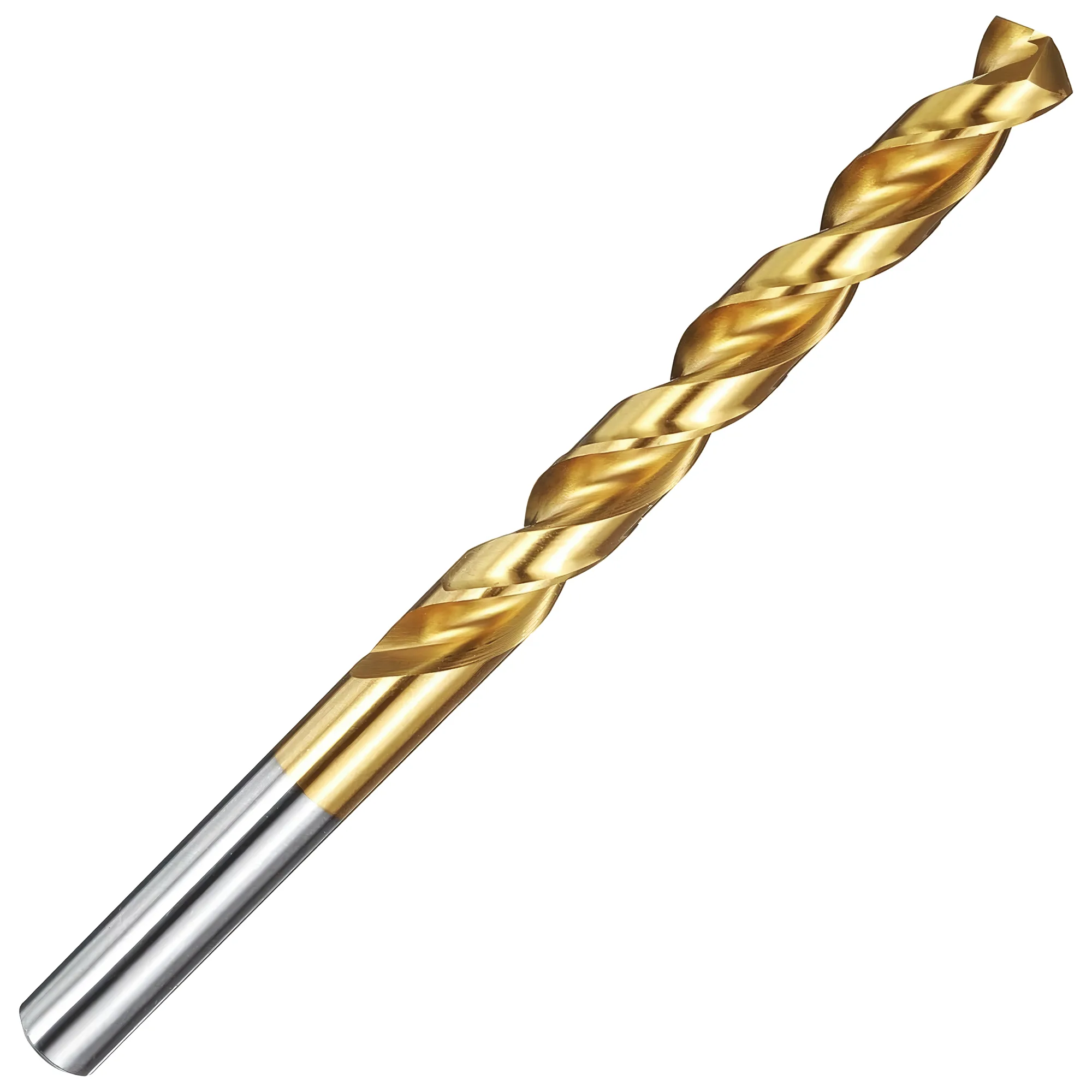
For drill bits (jobber, center, step) and reamers (spiral flute, straight flute), including HSS-Co vs carbide selection and H7 tolerance guidance, see the drill bit and reamer selection guide.
Indexable vs Solid — Decision Framework
One of the most fundamental decisions in cutting tool selection is whether to use indexable tools (replaceable inserts on a reusable body) or solid tools (one-piece construction, typically solid carbide). Solid carbide tools are typically chosen below 12 mm diameter because inserts that small become fragile, while indexable tools dominate above 16 mm because the cost-per-edge advantage from multi-edge inserts exceeds the rigidity benefit of a monolithic shank.
| Factor | Indexable Tools | Solid Carbide Tools |
|---|---|---|
| Tool Diameter Range | 12mm and above (typical) | 0.5-25mm (sweet spot 1-16mm) |
| Edge Count per Tool | 2-8 edges per insert | 1 edge (resharpenable 2-3x) |
| Edge Sharpness | Moderate (insert pressing limits) | Very sharp (ground geometry) |
| Cost per Cutting Edge | Lower at scale | Lower for small diameters |
| Rigidity | Lower (insert pocket tolerance) | Higher (monolithic) |
| Surface Finish | Good to excellent (with wiper) | Excellent (sharp ground edge) |
| Changeover Time | Seconds (rotate or swap insert) | Minutes (tool change + offset) |
Insert shape, size, and geometry designations follow ISO 1832, which is required when ordering or substituting indexable inserts across manufacturers because it standardizes the code that encodes nose angle, relief angle, tolerance class, and chip-breaker style (e.g., CNMG 120408 for an 80° diamond, 0° clearance, M-tolerance, flat-chip-breaker insert).
Use indexable tools when:
- Tool diameter is typically above 16mm (though small-diameter indexable tools are increasingly available)
- Production volume justifies insert inventory
- Multiple operations use the same insert geometry (standardization)
- Quick edge changes minimize machine downtime
- Heavy roughing where insert toughness matters
Use solid carbide tools when:
- Tool diameter is below 12mm (inserts below this size are fragile)
- Maximum rigidity is required (finishing, thin walls, tight tolerances)
- Surface finish demands the sharpest possible edge geometry
- Complex geometries (ball nose, corner radius, variable helix) are needed
- High-speed machining where monolithic construction prevents insert movement
The Crossover Zone
For diameters between 12mm and 20mm, both options are viable. The deciding factor is usually production volume: indexable tools win when you are consuming more than 10 edges per month at a given diameter, because the cost per edge drops below solid carbide even accounting for slightly lower rigidity.
In many shops, the most effective strategy is a hybrid approach: solid carbide end mills for finishing and small-diameter work, indexable face mills and shoulder mills for roughing and large-diameter operations, and indexable boring bars for internal machining. This minimizes both tooling cost and changeover time.
Putting It All Together — Selection Sequence
Cutting tool selection always starts with workpiece material because material determines the ISO 513 application group, which in turn narrows the substrate, coating, and geometry options before any specific brand is considered. Regardless of the specific tool category, every cutting tool selection follows the same logical sequence:
- Identify the workpiece material — this determines the ISO application group (P, M, K, N, S, H) and narrows the coating and substrate options immediately
- Define the operation — roughing, finishing, slotting, profiling, threading, or boring each demand different geometries and flute counts
- Check machine capability — spindle speed, torque, rigidity, and coolant system constrain what tools and parameters are feasible
- Select substrate and grade — carbide for CNC production, HSS for prototyping or high-breakage-risk operations, ceramic/CBN for hardened materials
- Choose coating — CVD for continuous high-speed cuts, PVD for interrupted operations and sharp edges, uncoated or DLC for aluminum
- Set geometry — shortest possible stickout, appropriate helix/lead angle, largest feasible diameter for boring
- Start with manufacturer recommendations — then optimize based on measured wear patterns in your specific conditions
For the wear-measurement workflow (VB monitoring, parameter adjustments, and Taylor-equation-based life prediction) that turns step 7 into a repeatable process, see the CNC tool life optimization guide.
Quick Cutting Tool Selection by Application
| Scenario | Tool Type | Material | Coating | Why |
|---|---|---|---|---|
| Roughing 1045 carbon steel pocket, 16 mm tool | 4-flute solid carbide end mill | Micrograin Tungsten Carbide, 10% Cobalt | PVD TiAlN | TiAlN's hot hardness above 800 °C handles the heat of P-group steel roughing while compressive stress survives ramping engagement |
| Continuous turning 4140 prehard at 280 m/min | CNMG indexable insert per ISO 1832 | P25 grade carbide | CVD (TiN/MT-TiCN/Al2O3) | Al2O3 thermal barrier protects the P-group substrate from crater wear that dominates above 200 m/min in alloy steel turning |
| Finishing 304 stainless slot, 6 mm tool | 4-flute solid carbide end mill, large flute valleys | Submicron Tungsten Carbide | PVD AlCrN | AlCrN resists notch wear and built-up edge that dominate M-group austenitic stainless because Cr-oxide slows diffusion at the depth-of-cut line |
| Face milling gray cast iron at 350 m/min | 45° face mill, K-group inserts per ISO 6462 arbor | K10 carbide | CVD with thick Al2O3 | K-group is engineered for abrasive flank wear from cast iron, and thick Al2O3 layer extends life by absorbing flank abrasion |
| Aluminum HSM at 800 m/min, 10 mm tool | 2- or 3-flute solid carbide end mill, 45° helix | Submicron Tungsten Carbide | Uncoated polished or DLC | DLC prevents the built-up edge that TiAlN promotes on aluminum, and large flute valleys clear long stringy chips |
| Deep boring 32 mm bore, 5:1 L/D in steel | Solid carbide boring bar, 90° lead | Solid carbide (580-620 GPa) | PVD TiAlN | Solid carbide stiffness offsets the 15.6x deflection penalty of 5:1 L/D and 90° lead directs forces axially to suppress chatter |
| Hardened H13 (54 HRC) finishing | Solid carbide ball nose end mill | Submicron Tungsten Carbide, low Cobalt | PVD TiSiN | TiSiN nanocomposite hardness above 4,000 HV resists abrasive wear in H-group hardened steel where toughness matters less than hardness |
| Inconel 718 turning at 50 m/min | CNMG insert per ISO 1832 | S-group carbide, fine grain | PVD AlCrN | S-group is engineered for nickel-superalloy notch wear and AlCrN's Cr-oxide layer resists the diffusion wear that dominates in nickel alloys |
Match every tool specification to your material and operation, then optimize from measured results.
The right cutting tool is never a single variable — it is the combination of substrate, coating, geometry, and parameters matched to your specific workpiece material and operation type. Start with ISO 513 for grade selection, choose CVD for continuous heat and PVD for interrupted edges, use the largest boring bar diameter that fits, and select flute count by material. Get these fundamentals right and you eliminate 80% of tool life problems before they start.
How do I know when a cutting tool needs to be replaced?
Monitor flank wear width — most carbide inserts should be indexed or replaced at 0.3mm flank wear (VB = 0.3mm per ISO 3685). Other signals include degrading surface finish, increasing cutting forces (audible change in sound), and dimensional drift in the workpiece. Never run to catastrophic failure, as this damages the workpiece and can harm the machine spindle.
Can I use the same carbide grade for turning and milling?
Generally no. Turning is continuous cutting that generates sustained heat, favoring CVD-coated grades optimized for crater wear resistance (P15-P25). Milling involves repeated interrupted engagement that thermally shocks the edge, favoring PVD-coated grades with compressive residual stress (P20-P30). Some manufacturers offer dual-purpose grades, but dedicated grades outperform them in most applications.
What is the most cost-effective way to improve tool life?
In order of impact: (1) ensure correct ISO grade for your material, (2) verify cutting speed is within the recommended range for the grade and coating, (3) use the shortest possible tool stickout to maximize rigidity, and (4) optimize coolant delivery to the cutting zone. These four steps cost nothing beyond setup time and typically yield 30-50% tool life improvement.
Should I always choose coated over uncoated carbide?
Not always. Uncoated polished carbide or PCD is preferred for aluminum machining, where coatings like TiAlN can chemically react with the workpiece and accelerate built-up edge formation. Uncoated tools also suit some plastic and composite applications. For steel, stainless, cast iron, and superalloys, coated tools are virtually always superior.
How do I choose between a 2-flute and 4-flute end mill?
Choose by workpiece material: aluminum requires 2-3 flutes so the large flute valleys evacuate long, stringy chips. Steel and stainless accept 4-5 flutes because their shorter chips clear more easily, and more flutes raise the achievable table feed rate. For slotting in any material, drop to fewer flutes to prevent chip packing.
Sources
- ISO 513:2004 — Classification and Application of Hard Cutting Materials for Metal Removal
- ISO 3685:1993 — Tool Life Testing with Single-Point Turning Tools
- ISO 8688-1:1989 — Tool Life Testing in Milling, Part 1: Face Milling
- Machinery's Handbook, 31st Edition (Industrial Press)
- Sandvik Coromant: Metalcutting Technical Guide