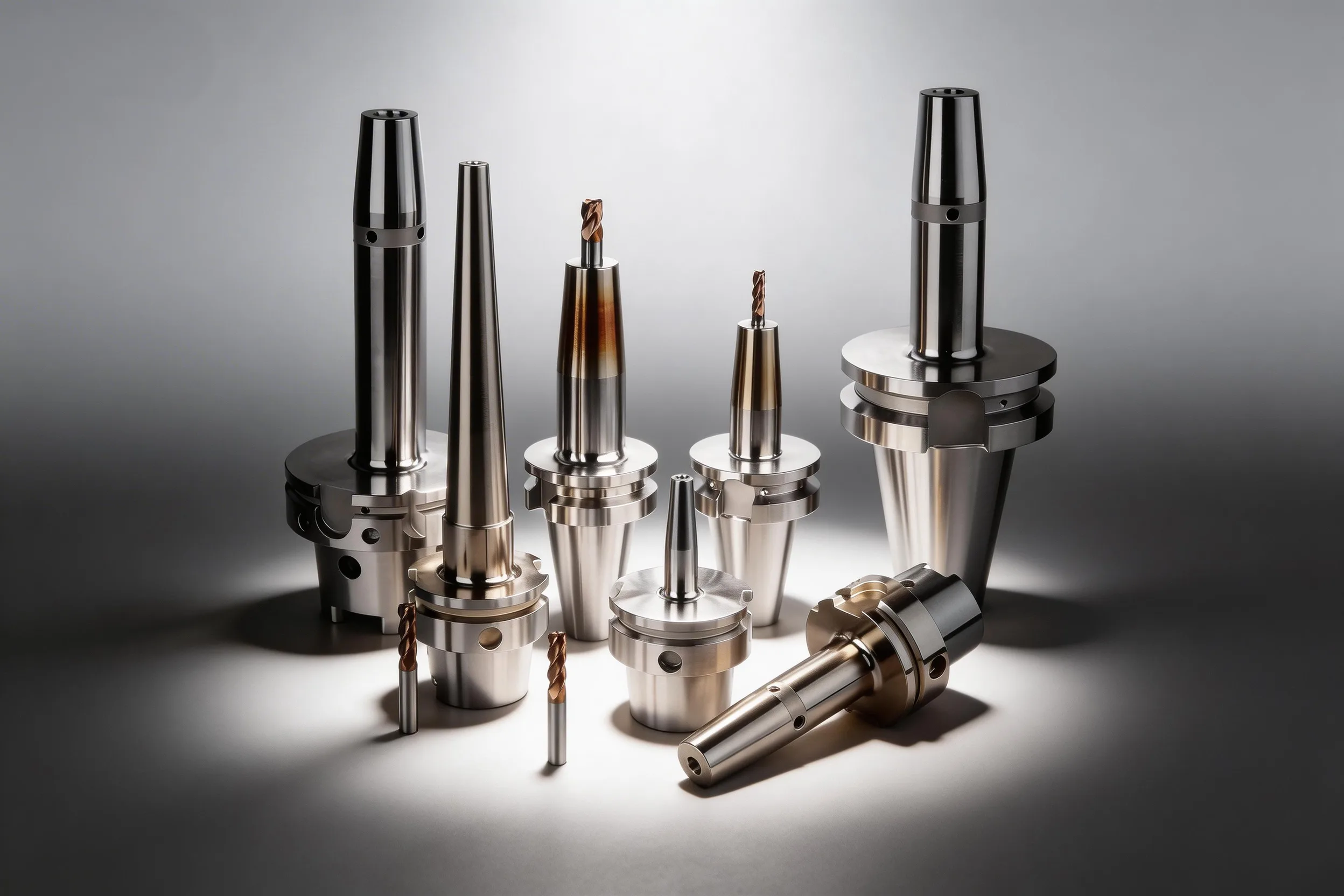
Machining chatter costs shops 15–30% of productive spindle time through scrapped parts, premature tool wear, and unplanned stops — yet most chatter problems can be resolved without new equipment. Identify the chatter frequency first: tool-tooth frequency (Ω × flutes) indicates forced vibration; non-integer multiples of tooth frequency indicate self-excited regenerative chatter. For regenerative chatter, shift spindle speed to a stability lobe pocket — typically a 10–20% speed change moves the operating point from an unstable zone to a stable one with no depth-of-cut penalty.
Quick Chatter Reference
| Problem / Goal | Primary Action | Expected Impact |
|---|---|---|
| Audible squeal at tool-tooth frequency | Check tool overhang — shorten by 20–30% | Deflection drops ~2–3× (L³ relationship — halving overhang gives ~8×); chatter often eliminates immediately |
| Regenerative chatter at non-integer frequency | Shift spindle speed ±10–15% to next stability lobe | Achieves same MRR with stable cut; typical axial DoC improvement 1.5–3× |
| Chatter resurfaces after speed change | Reduce axial depth of cut to below stability limit, then raise speed | Enters unconditionally stable zone; tool life normalises to baseline |
| Workpiece flexing (thin wall or slender part) | Add auxiliary support or increase fixtures contact area | Reduces dynamic compliance at workpiece by 40–70% in typical setups |
| Holder runout above 0.010 mm | Replace with shrink-fit or hydraulic holder | Runout-driven forced vibration cut to ≤0.003 mm TIR; tool life recovers 20–40% |
| Chatter only at full spindle depth | Switch to variable-helix or serrated-edge end mill | Phase disruption reduces chatter onset depth by 2–3× vs uniform-helix tool |
Understanding Chatter: Two Mechanisms, Two Diagnoses
Chatter is a dynamic instability between the cutting tool and workpiece. Forced vibration and self-excited regenerative chatter look similar to the ear but require different fixes. Confusing them wastes time and money.
Forced vibration occurs when an excitation frequency matches or is near a structural resonance. The dominant frequency in the sound or vibration signal is an integer multiple of spindle speed: tooth-passing frequency = (RPM / 60) × number of flutes. Typical sources include imbalance in the spindle-holder-tool assembly, unequal flute spacing, or worn spindle bearings. Forced vibration amplitude scales with the excitation force — reducing cutting forces (lower feed or depth) attenuates the symptom without addressing the root cause.
Regenerative chatter is a self-excited instability. The tool cuts over the wavy surface left by the previous tooth pass; this waviness modulates the chip thickness, which in turn modulates the cutting force, which re-excites the vibration. The frequency of regenerative chatter is not an integer multiple of the tooth-passing frequency — it typically falls between two tooth-pass harmonics. Regenerative chatter grows until the system reaches a limit cycle (constant-amplitude vibration), which produces characteristic lobed surface patterns and rapid flank wear.
Diagnosing with a Microphone or Accelerometer
A smartphone FFT app (or a simple data logger with a microphone) is sufficient for initial diagnosis on the shop floor:
- Record audio or vibration during a stable reference cut (light pass, no chatter).
- Record during the problem cut.
- Compare spectra: peaks at exact tooth-pass harmonics → forced vibration; peaks between harmonics (non-integer ratios) → regenerative chatter.
Tooth-pass frequency (Hz) = (spindle speed in RPM / 60) × number of flutes. For a 4-flute end mill at 6,000 RPM: tooth-pass frequency = (6,000/60) × 4 = 400 Hz. Any dominant peak near 400 Hz, 800 Hz, or 1,200 Hz is likely forced vibration; a dominant peak at 550 Hz with no harmonic relationship to 400 Hz is regenerative chatter.
Stability Lobe Diagrams: Using Speed to Escape Chatter
The stability lobe diagram (SLD) maps the boundary between stable and unstable cutting in spindle-speed vs. axial-depth-of-cut space. Above the stability boundary, regenerative chatter grows; below it (or within a lobe "pocket"), the cut is stable. Stability lobe diagrams show that specific spindle speed ranges — lobe pockets — allow cutting depths 2–4× deeper than the average stable limit.
How the SLD Works
The stability limit depends on the ratio of the chatter frequency to the tooth-pass frequency. When the spindle speed is set so the tooth-pass period equals the period of the chatter vibration (or a sub-harmonic), the phase of the wavy surface re-entering the cut is 180° — the chip thickness variation is cancelled, and the cut is maximally stable. These conditions correspond to the peaks (lobes) of the SLD.
The lobe number k and the stable spindle speed N are related by:
N (RPM) = 60 × f_c / (k × z)
where f_c is the chatter frequency in Hz, k is the lobe number (integer ≥ 1), and z is the number of flutes. Chatter frequency dominates stability: every 1% change in chatter frequency shifts the optimal spindle speed by 1%, so accurate frequency measurement is the critical first step. For example, at f_c = 550 Hz, z = 4, k = 1: N = 60 × 550 / (1 × 4) = 8,250 RPM. At k = 2: N = 4,125 RPM.
Constructing a Shop-Floor SLD Without Software
A full SLD requires dynamic stiffness measurements (tap testing). A simplified shop-floor approach:
- Identify chatter frequency f_c from audio/vibration spectrum.
- Calculate the first three lobe speeds: N_k = 60 × f_c / (k × z) for k = 1, 2, 3.
- Run a brief trial at each N_k with axial depth increased by 25% over the failed depth.
- The lobe speed that runs stably is your operating point; all others are likely unstable.
Lobe Speed Shortcut
Once you find the highest stable spindle speed (k=1), the next stable speed is exactly half (k=2), and the one after is one-third (k=3). Use this arithmetic to quickly bracket speeds for a trial without measurement software.
Why Depth Increase Works at Lobe Centers
At a lobe-center speed, the regenerative phase is constructively stable — the system's closed-loop gain is below unity. Raising depth of cut to 150% of the average stability limit is often feasible in a lobe pocket, increasing MRR proportionally while maintaining stable conditions. This effect diminishes near lobe boundaries, where stability deteriorates rapidly.
Tooling Solutions: Reducing Dynamic Compliance at the Source
If speed adjustment alone does not resolve chatter — common in low-RPM heavy roughing or when the spindle lacks speed flexibility — the problem is excessive dynamic compliance in the tooling system. Tooling-side compliance is dominated by the overhang-to-diameter (L/D) ratio: compliance scales with L³, so reducing overhang from 4×D to 3×D cuts dynamic deflection by approximately 2.4×. The same L³ scaling applies in boring bar selection, where it is the primary driver of vibration control in long-reach applications.
Overhang Control
Minimum effective overhang is the most impactful single tooling change. Keep total tool projection (shank + flute) as short as the geometry allows:
- For side milling with a 16 mm end mill: maximum recommended overhang is 3–4×D (48–64 mm) for steel; reduce to 2.5×D for titanium or nickel alloys.
- Every 10% reduction in overhang reduces deflection by ~30% (from d ∝ L³: (0.9)³ ≈ 0.73, Δ ≈ 27%).
- Use stub-length end mills when feature depth allows; switch to screw-on or modular heads rather than long-reach solid carbide when access permits.
Tool Holder Rigidity: Shrink-Fit and Power Chuck
Holder choice affects both static stiffness and damping. Shrink-fit holders conform to ISO/DIN 69893 geometry tolerances and deliver radial runout ≤0.003 mm TIR at 3×D, reducing forced vibration excitation by keeping chip loads balanced across flutes. See the tool holding complete guide for a full runout comparison across holder types.
HSK-C power milling chucks provide a hybrid clamping mechanism — a precision bore with high clamping force — that combines the runout accuracy of shrink-fit with the flexibility to change tools without an induction heater. Power milling chucks are preferred for heavy-interrupted cuts because the mechanical clamping prevents micro-slippage that can amplify dynamic force peaks under shock loading.
Variable-Helix and Serrated End Mills
For cases where speed shifting and overhang reduction are insufficient, variable-helix end mills disrupt the phase relationship between consecutive flute passes. Variable-helix tools distribute the regenerative feedback across multiple frequencies, raising the effective stability limit by 1.5–2.5× in axial depth compared to equal-helix tools under equivalent conditions. Serrated (roughing) end mills break the chip into short segments, reducing peak cutting force and lowering the effective excitation amplitude — particularly useful in aluminum and softer steels at high MRR.
Fixturing Solutions: Reducing Dynamic Compliance at the Workpiece
Chatter is a system property — the tool and workpiece are coupled springs. Even a perfect tool setup chatters if workpiece compliance is high. In thin-wall and slender workpiece setups, the workpiece modal compliance is frequently the dominant contributor to chatter onset, not the tool.
Increasing Fixture Contact and Preload
The dynamic stiffness of a workpiece in a vise or chuck is proportional to the clamping force and contact area. For modular precision vises (e.g., GT-series), use the following:
- Serrated jaws increase friction coefficient by 30–50% over smooth jaws, providing higher effective clamping stiffness at the same actuating torque.
- Maximum jaw spread within the jaw's rated capacity increases the static moment arm and resists part rocking under cutting loads.
- Dual-vise or tandem setup: for long prismatic parts, a second vise at the far end eliminates the cantilever deflection that often initiates chatter.
Precision modular vises that provide repeatable jaw positioning to ±0.005 mm reduce workpiece resonant frequency variation between setups, preventing chatter conditions that are inconsistent and hard to diagnose.
Auxiliary Support and Damping
For thin walls and deep pockets:
- Jaw supports: conforming custom soft jaws increase contact area 3–5× over standard hardened jaws, distributing the clamping force and raising dynamic stiffness.
- Low-melting alloy fill (bismuth alloy): filling the thin-wall cavity with a low-temperature alloy (melt at ~70°C) provides broadband structural damping; effective in aerospace titanium and nickel alloy thin-wall parts where fixture access is limited.
- Tunable damping plugs: for slender parts with a known chatter frequency, a tuned mass damper in the workpiece cavity or held in a tool holder reduces the compliance peak by 5–15 dB at the target frequency.
Do Not Rely on Feed Rate Reduction Alone
Reducing feed rate lowers surface quality signal amplitude but does not address the regenerative mechanism. Chatter frequently re-emerges once feed is restored. Feed reduction is a temporary diagnostic tool — not a fix. The root cause must be resolved via speed selection, overhang reduction, or fixturing.
Parameter Guide: Chatter Frequency, Lobe Speed, and Overhang Limits
| Tool Diameter (mm) | Max Recommended Overhang | Steel (L/D) | Titanium (L/D) | Chatter Risk |
|---|---|---|---|---|
| 6 | 18 mm | 3× | 2.5× | High above 3× |
| 10 | 35 mm | 3.5× | 2.5× | High above 3.5× |
| 16 | 56 mm | 3.5× | 3× | Moderate at 3–4× |
| 20 | 70 mm | 3.5× | 3× | Moderate at 3–4× |
| 32 | 128 mm | 4× | 3× | Low risk at 4× in rigid setups |
| Chatter Frequency (Hz) | 4-Flute Lobe 1 (RPM) | 4-Flute Lobe 2 (RPM) | 2-Flute Lobe 1 (RPM) |
|---|---|---|---|
| 400 | 6,000 | 3,000 | 12,000 |
| 550 | 8,250 | 4,125 | 16,500 |
| 800 | 12,000 | 6,000 | 24,000 |
| 1,100 | 16,500 | 8,250 | 33,000 |
| 1,500 | 22,500 | 11,250 | 45,000 |
Lobe RPM values are theoretical centers. In practice, stable zones span ±5–8% around these values.
HSK Interfaces for High-Speed Lobe Targeting
High-RPM lobe pockets (above 15,000 RPM for a 4-flute tool with typical chatter frequencies of 800–1,500 Hz) require HSK interfaces rather than BT/CAT due to the centrifugal expansion issue above 12,000 RPM. DIN 69893-compliant HSK-A and HSK-C interfaces maintain dual face-and-taper contact at high RPM, preserving the stiffness required to keep the operating point inside the stability lobe.
Systematic Chatter Elimination Checklist
Apply fixes in this order — each step eliminates the most common cause before escalating to more complex solutions:
- Measure the frequency — use FFT (phone app sufficient). Classify: tooth-pass harmonic = forced; non-harmonic = regenerative.
- Check overhang — if L/D > 3.5× for the workpiece material, shorten before anything else.
- Check runout — if runout > 0.010 mm, switch holder type (shrink-fit or power chuck).
- For regenerative chatter — calculate three lobe speeds from f_c; trial each at +25% axial DoC.
- Check workpiece compliance — apply supplementary clamping or auxiliary support if the part deflects visibly during probing.
- Escalate — variable-helix end mill, tuned damper, or tap-test + full SLD if above steps fail.
Following this six-step sequence resolves 80–90% of field chatter problems without requiring specialized vibration analysis software or external consultation, based on typical shop floor experience. For optimising cutting speed and feed rate alongside chatter control, the CNC machining optimization guide covers Taylor tool life and parameter selection in detail.
Frequency first, lobe second, compliance third.
Diagnose chatter by FFT frequency pattern before changing anything. Regenerative chatter requires a spindle speed shift to a stability lobe pocket — a 10–20% speed change typically moves from unstable to stable operation. If speed alone is insufficient, reduce tool overhang (primary tooling fix) or increase fixture contact area (primary workholding fix). Shrink-fit and HSK-C power chuck holders reduce runout to ≤0.003–0.005 mm, eliminating the forced vibration contribution and giving lobe-based speed selection the clean dynamic environment it requires.
How do I know if my chatter is regenerative or forced vibration?
Record audio during the cut and use a free FFT app to identify the dominant frequency. If it falls at an integer multiple of tooth-pass frequency (RPM/60 × flutes), it's forced vibration — check runout and balance. If it falls between tooth harmonics at a non-integer ratio, it's regenerative chatter — apply stability lobe speed selection.
What spindle speed should I use to avoid regenerative chatter?
Calculate lobe-center RPM as 60 × chatter_frequency_Hz / (lobe_number × flute_count). For a 4-flute tool with 550 Hz chatter, the first lobe is at 8,250 RPM. Trial ±5–8% around that value while increasing axial depth of cut by 25%. If the cut runs quietly, you've found a stable pocket; if not, try the next lobe at half speed (4,125 RPM).
Does reducing feed rate fix chatter?
Feed rate reduction attenuates symptom amplitude temporarily but does not resolve the regenerative mechanism. Once feed is restored, chatter typically returns. Use feed reduction only as a diagnostic step to confirm the cut is otherwise acceptable, then address the root cause through speed selection, overhang reduction, or fixturing.
How much does shortening tool overhang help with chatter?
Cantilever deflection scales with L³, so every 10% reduction in overhang cuts deflection by approximately 27%. Shortening from 4×D to 3×D reduces deflection by 58%, and from 4×D to 2×D reduces it by 87%. In practice, halving overhang typically eliminates chatter in steel for tools up to 20 mm diameter at standard milling parameters.
When should I use a shrink-fit holder vs. a power milling chuck for chatter reduction?
Use shrink-fit holders for maximum runout accuracy (≤0.003 mm TIR) in finishing and high-speed operations where tool changes are infrequent. Use HSK-C power milling chucks for heavy interrupted cuts and frequent tool changes, where their mechanical clamping resists micro-slippage under shock loads. Both outperform standard ER collets for chatter-sensitive applications.
Sources
- Altintas, Y. Manufacturing Automation: Metal Cutting Mechanics, Machine Tool Vibrations, and CNC Design. Cambridge University Press, 2012. (Stability lobe diagram derivation, Chapter 3)
- Schmitz, T.L. & Smith, K.S. Machining Dynamics: Frequency Response to Improved Productivity. Springer, 2009. (Lobe speed calculation method, Chapters 4–5)
- BIG DAISHOWA — The One Tenth = 10% Rule and Effects of Runout
- Sandvik Coromant — Milling Vibration and Chatter
- DIN 69893 — Hollow taper shanks with flange contact surface; HSK-A and HSK-B dimensions and tolerances