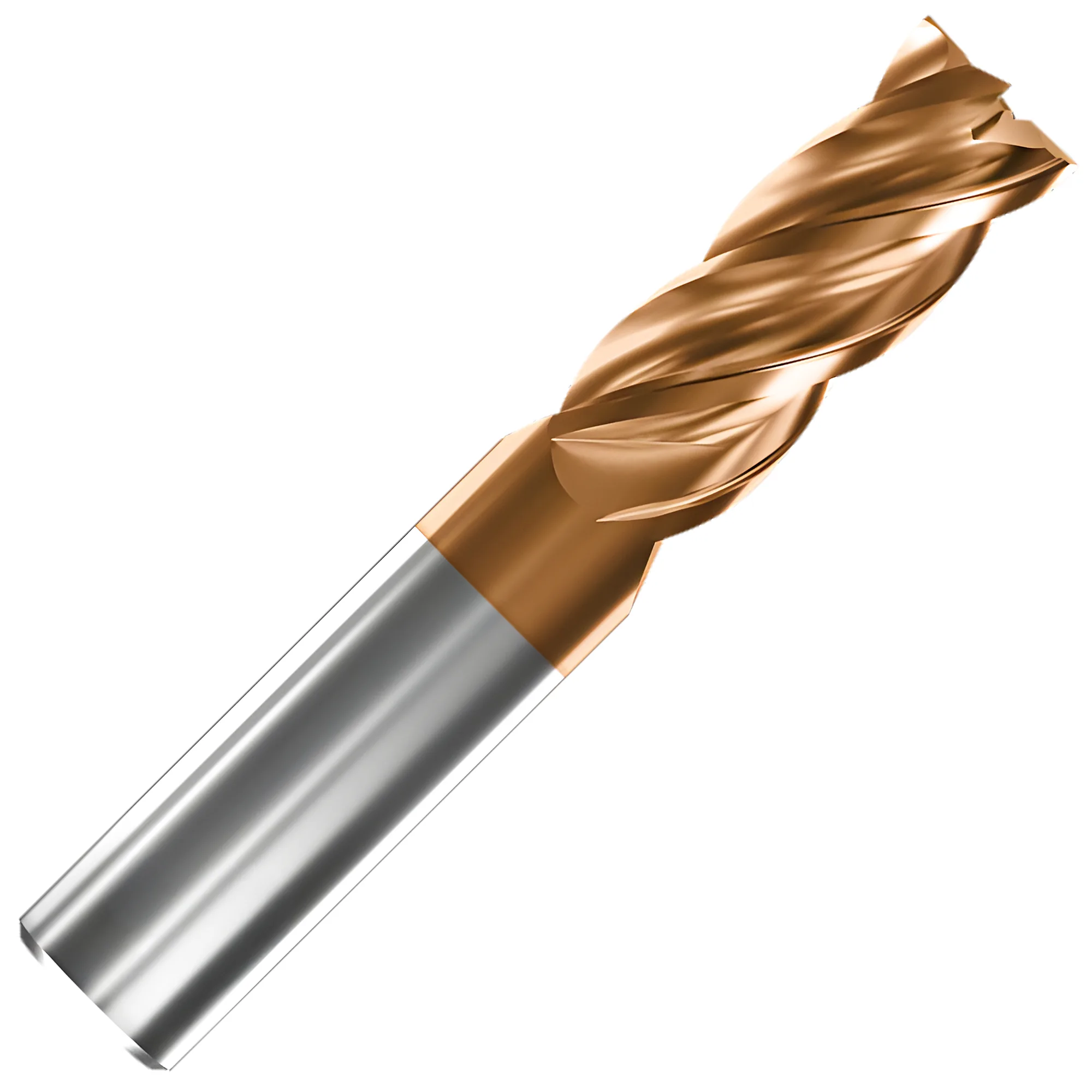
For a 12 mm (0.472 in) carbide square end mill in 4-flute configuration, begin with SFM 300–400 for low-carbon steel, SFM 800–1,200 for 6061 aluminum, and SFM 100–150 for 304 stainless; convert to RPM with RPM = (SFM × 3.82) / diameter (inches), then set chip load at 0.5–1.0% of cutter diameter per flute and adjust table feed as feed rate (IPM) = RPM × flute count × chip load. Radial depth of cut (RDOC) adjustments can extend carbide end mill tool life by 2–4× compared to running full-slot cuts at the same SFM.
Quick Feeds and Speeds Reference
| Problem / Goal | Primary Action | Expected Impact |
|---|---|---|
| Tool life too short in steel | Reduce SFM 10% and verify chip load ≥ 0.005 in/tooth | ~1.5–2× tool life (Taylor n≈0.14–0.25 for carbide in steel) |
| Chatter on slender end mill | Reduce RDOC to 10–15% of cutter diameter | Radial force drops ~40–60%, vibration collapses |
| Chip re-cutting / built-up edge in aluminum | Increase SFM to 800–1,000, use ZrN-coated end mill | BUE eliminated; surface finish Ra improvement 50–70% |
| Poor surface finish in finish pass | Reduce chip load 30–40% below roughing value | Ra ∝ feed² — halving chip load cuts Ra by ~75% |
| Overloaded spindle in stainless | Reduce ADOC (axial depth) before SFM | Radial cutting force reduced; heat generation drops more than speed reduction alone |
| Catastrophic end mill breakage | Verify RDOC ≤ 50% diameter in full-slot; reduce to 30–40% | Chip thinning prevents overload; most breakage in milling occurs at full-width entry |
Understanding the Three Core Parameters
Cutting speed (SFM or Vc), chip load (fz), and radial engagement (RDOC) are the three independent variables that govern carbide end mill performance — changing any one shifts the balance among tool life, surface finish, and material removal rate. See the end mill selection guide for choosing flute count, substrate, and geometry before setting parameters.
Surface Footage (SFM / Vc)
Surface feet per minute (SFM) is the linear velocity of the cutting edge through the workpiece material. It drives heat generation and is the dominant variable in tool wear because carbide hardness decreases rapidly above 700–800°C. The formula is:
SFM = (RPM × D × π) / 12 (for diameter in inches)
Or rearranged to set RPM from a target SFM:
RPM = (SFM × 3.82) / D
SFM is the dominant variable in the Taylor tool-life equation VT^n = C — SFM dominates tool life because it governs cutting temperature, and for carbide in steel, a 10% SFM reduction can increase tool life by 1.5–2.1× depending on feed rate and material hardness.
Chip Load (fz)
Chip load is the thickness of material removed per tooth per revolution, measured in inches per tooth (IPT) or mm/tooth. It drives cutting force, torque, and surface finish. The conversion to table feed rate is:
Feed (IPM) = RPM × Z × fz
where Z is the number of flutes. Chip load is typically set at 0.5–1.0% of cutter diameter for roughing in steel and 0.3–0.5% for finishing. Chip load appears squared in the theoretical surface roughness formula, so chip load directly determines achievable Ra in finish passes: Ra (theoretical) = fz² / (32 × r), where r is nose radius — feed dominates surface finish because it appears squared; halving chip load reduces Ra by approximately 75%.
Radial Depth of Cut (RDOC) and the Chip-Thinning Effect
Radial depth of cut (RDOC) determines the arc length each tooth spends in cut, and reducing it below 50% of cutter diameter creates a chip-thinning effect that allows higher table feeds without overloading the tool.
When RDOC drops below 50% diameter, the actual chip thickness at the tooth center becomes thinner than the programmed chip load. The chip-thinning factor (CTF) is:
CTF = √(RDOC / (D/2))
At RDOC = 25% diameter, CTF ≈ 0.707 — the actual chip is 30% thinner than programmed. To maintain the intended material removal rate, compensate by multiplying chip load by 1/CTF ≈ 1.41. At RDOC = 10% (high-efficiency milling or trochoidal), CTF ≈ 0.447, so the compensated chip load is 2.24× the baseline — achieving the same tool load at a table feed rate 2.24× higher than the uncompensated value.
Starting Parameters by Material Group
ISO 513 material groups provide a reliable starting framework: P (steel), M (stainless), K (cast iron), N (non-ferrous), S (heat-resistant alloys) each require distinct SFM ranges and chip loads.
P-Group: Carbon and Alloy Steel (<300 BHN)
| Cutter Diameter | SFM (Vc) | Chip Load per Tooth | RDOC (Roughing) |
|---|---|---|---|
| 6 mm (0.25 in) | 275–375 SFM | 0.0015–0.003 in | 40–50% D |
| 12 mm (0.50 in) | 300–400 SFM | 0.003–0.006 in | 40–50% D |
| 19 mm (0.75 in) | 300–425 SFM | 0.004–0.008 in | 35–50% D |
| 25 mm (1.00 in) | 300–425 SFM | 0.005–0.010 in | 35–50% D |
For 4140 alloy steel (28–32 HRC), reduce starting SFM by 15–25% versus low-carbon steel. For hardened steel (45–55 HRC), use a TiAlN-coated end mill and target SFM 120–200 with RDOC 10–15% diameter.
N-Group: Aluminum Alloys
Aluminum alloys require 3–5× the SFM of steel because aluminum's low thermal conductivity demands rapid chip evacuation through speed, not coolant volume. For 6061-T6 and 7075-T6, start at SFM 800–1,200 with 2-flute or 3-flute end mills (to maximize chip room), chip load typically 0.005–0.012 in/tooth (varies with cutter diameter and machine rigidity), and RDOC 50–75% diameter. ZrN coatings are preferred for aluminum because their low coefficient of friction (0.35 vs 0.7 for uncoated carbide) prevents aluminum adhesion and built-up edge formation.
M-Group: Stainless Steel (300 Series)
Austenitic stainless work-hardens during cutting — the surface hardness rises from ~200 HV to 350+ HV in the first 0.1 mm of depth if the tool dwells or rubs without cutting. For 304/316 stainless, the chip load floor is 0.003–0.004 in/tooth for a 12 mm end mill — going below this threshold risks rubbing rather than cutting, accelerating work hardening and edge wear. Use SFM 100–150 with TiAlN-coated 4-flute end mills and maintain consistent feed engagement through full passes.
S-Group: Titanium Alloys
Ti-6Al-4V requires the most conservative parameters: SFM typically 30–60 m/min (98–197 SFM) per industry experience, chip load 0.05–0.10 mm/tooth (0.002–0.004 in/tooth), and RDOC 10–30% diameter with climb milling as the production standard. High-pressure coolant (70–140 bar) is the production standard to prevent heat soaking into the tool because titanium's thermal conductivity is one-tenth that of aluminum — heat concentrates at the tool-chip interface rather than dispersing through the chip.
The Taylor Equation and SFM Reduction for Tool Life
The Taylor tool-life equation VT^n = C quantifies the trade-off between cutting speed and tool life, and for carbide end mills in steel, a 10% SFM reduction typically yields 1.5–2.1× longer tool life depending on feed rate.
The exponent n characterizes how steeply tool life responds to speed changes:
- Soft steel (<300 BHN, small feed): n ≈ 0.14 — a 10% speed drop gives ~2.1× life
- Alloy steel (>300 BHN, medium feed): n ≈ 0.20–0.25 — a 10% drop gives ~1.5–1.8× life
The calculation: T₂/T₁ = (V₁/V₂)^(1/n). At V₂ = 0.9 × V₁ (10% reduction) and n = 0.14: T₂/T₁ = (1/0.9)^(1/0.14) = 1.111^7.14 ≈ 2.1× tool life.
The ISO 3685:1993 standard defines tool replacement criteria: average flank wear VB_B = 0.3 mm for finishing operations and VB_B max = 0.6 mm for roughing. Use these thresholds to set consistent tool change intervals rather than running to catastrophic failure, which introduces burrs and dimensional drift. The CNC tool wear monitoring guide covers practical wear inspection methods and replacement scheduling in detail.
Set SFM Low First, Then Step Up
When running a new carbide end mill in an unfamiliar material, start at 75% of the recommended SFM and measure flank wear after the first 10 minutes of cutting. If VB_B is below 0.1 mm, increase SFM by 10% increments. If VB_B reaches 0.2 mm in the first 10 minutes, reduce SFM and revisit chip load — the tool is heat-limited, not force-limited.
Radial Depth Strategies for Milling Operations
Square end mills, ball end mills, and bull-nose end mills each require different RDOC strategies because their cutting edge geometry affects chip formation and heat distribution differently.
Square End Mill RDOC
For carbide square end mills in slotting (RDOC = 100% diameter), cutting forces peak at tool entry and exit. Full-slot milling at SFM 350 in steel generates roughly 2× the heat per unit time as a 50% RDOC pass at the same SFM, because both edges engage simultaneously. Limit full-slot cuts to axial depths of 0.5–1.0× diameter and use flood coolant. For pocketing, trochoidal milling at RDOC 10–20% diameter allows 3–5× higher feed rates than conventional slotting at equivalent tool loads.
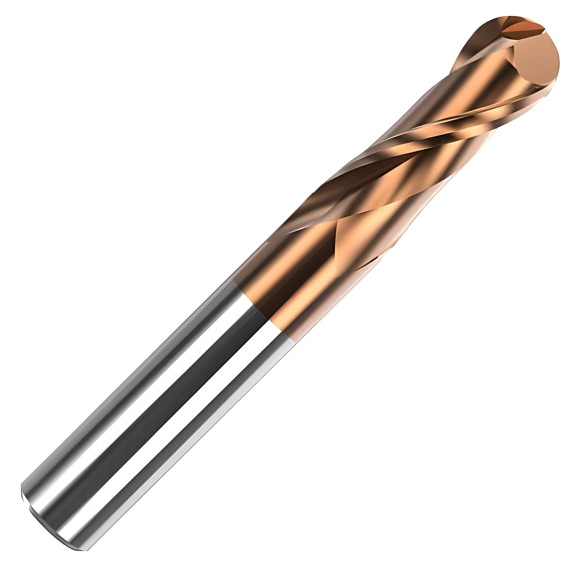
Carbide Ball End Mill and Scallop Height
For carbide ball end mills in 3D contouring, the effective cutting diameter shrinks at shallow axial depths — the formula is:
D_eff = 2 × √(ap × (D − ap))
where ap is axial depth and D is ball diameter. At ap = 0.5 mm with a 10 mm ball end mill, D_eff ≈ 4.4 mm. The actual chip load from the programmed SFM at the ball center may be only 44% of the programmed value at 10 mm diameter, so the spindle must spin faster than the nominal calculation suggests to maintain the target SFM at the effective cutting zone.
Scallop height (h) in ball-end finish passes is:
h = ae² / (8r)
where ae is step-over and r is ball radius — step-over dominates scallop height because it appears squared; halving step-over reduces scallop height (and Ra) by 75%, and is more effective than halving feed for surface improvement in 3D contouring passes.
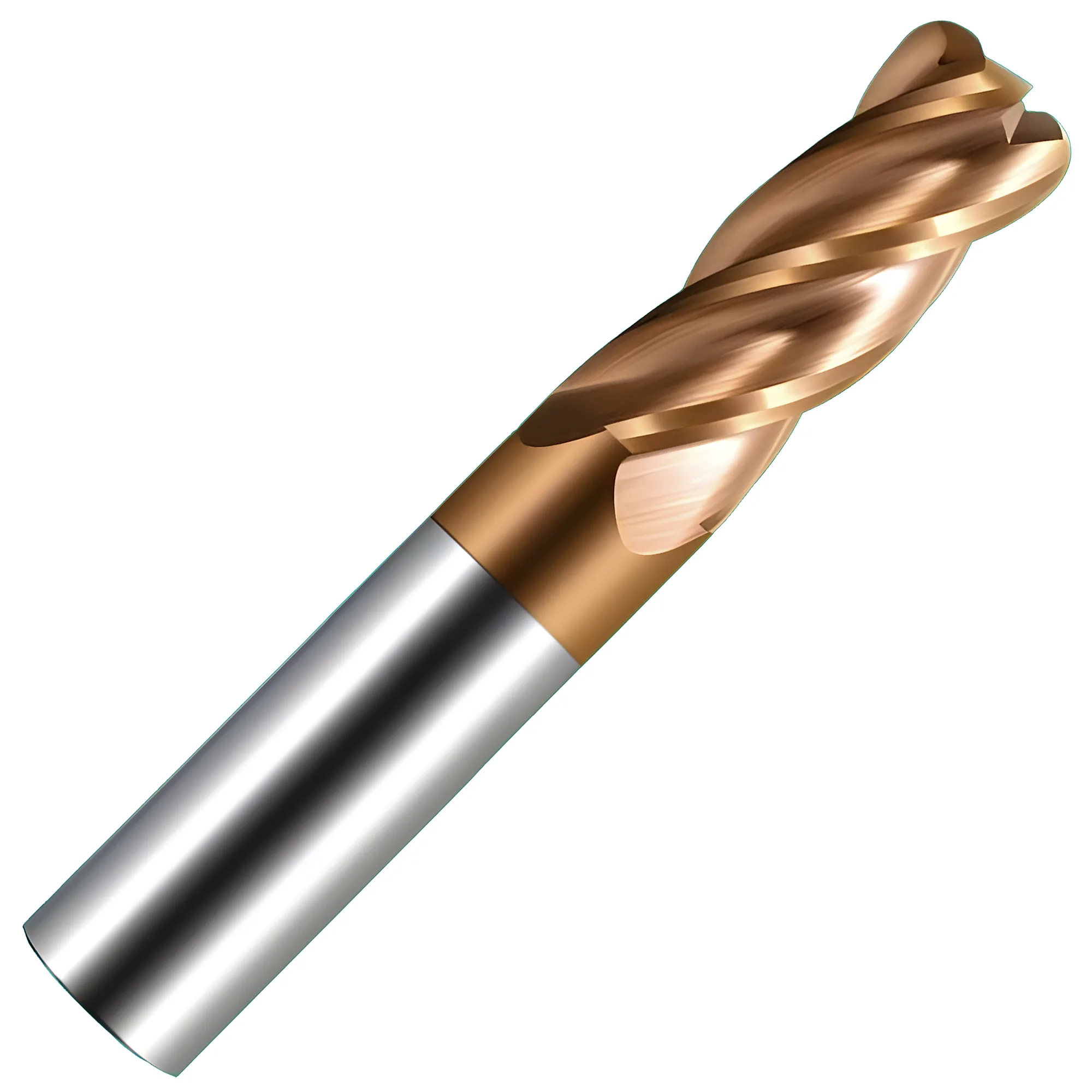
Bull-Nose End Mill Corner Radius Advantage
Carbide bull-nose end mills tolerate 20–40% higher chip loads than equivalent square end mills in the same material because the corner radius distributes cutting force over a larger arc length, reducing peak stress at the cutting edge.
For floor and shoulder finishing in steel, a bull-nose end mill with corner radius typically 0.5–1.0 mm (common catalog sizes) at SFM 350–425 and chip load 0.004–0.007 in/tooth produces Ra 0.8–1.6 µm without a dedicated finish pass in most rigid machine setups. The corner radius also prevents the micro-chipping at square corners that reduces tool life when plunging or engaging at depth.
Avoid Full Diameter Slotting with Long Reach End Mills
End mills with overhang exceeding 4× diameter deflect under full-slot cutting loads — deflection scales with L³ (beam deflection formula d = FL³/(3EI)), so doubling overhang from 2D to 4D increases deflection 8×. For overhang >3× diameter, reduce RDOC to 30–40% diameter and increase axial depth instead; this maintains material removal rate while cutting radial force by 40–60%.
Coating Selection and Its Effect on Starting Parameters
The right coating for a carbide end mill typically allows a 20–30% increase in SFM versus uncoated carbide in the same material, with the specific gain depending on whether the dominant failure mode is thermal or abrasive.
TiAlN for Steel and Hardened Alloys
TiAlN coatings carry a hardness of 3,000–3,500 HV and maintain oxidation resistance to 800°C, making them the preferred choice for carbide end mills in steel machining, particularly in semi-dry or dry conditions. TiAlN is preferred for dry milling of steel and hardened materials because its oxidation resistance at 800°C forms a protective Al₂O₃ layer at the cutting interface, slowing crater wear and allowing SFM 300–425 versus 225–325 for uncoated carbide. For interrupted cuts and milling of steel above 35 HRC, an AlTiN variant (higher aluminum content) provides better hardness retention above 900°C.
AlTiN for High-Temperature Applications
AlTiN coatings are used when cutting temperatures exceed the TiAlN stability threshold because their higher aluminum content (Al/Ti ratio ~67:33 vs TiAlN's ~50:50) raises the oxidation onset to approximately 900°C, extending usable SFM range in aerospace alloys and hardened steels by 15–25% compared to standard TiAlN.
ZrN for Aluminum and Copper
ZrN coatings are preferred for aluminum and copper alloys because their low coefficient of friction (0.35 versus 0.7 for uncoated carbide) and chemical inertness to aluminum prevent built-up edge formation at SFM 800–1,200. An uncoated carbide end mill in aluminum at SFM 1,000 will typically show BUE within 15–20 minutes; a ZrN-coated end mill at the same parameters may run 60–90 minutes without adhesion, representing a 3–5× improvement in effective tool life in production aluminum machining.
Building a Feed Rate Calculation Workflow
A systematic four-step calculation sequence — SFM selection → RPM → chip load → feed rate — eliminates the guesswork that leads to premature tool failure or underperforming cycle times.
Step 1: Select SFM from Material Group
Start with the ISO 513 group and material hardness, then apply a coating correction (+20–30% for TiAlN/AlTiN versus uncoated in steel). Use the lower end of the SFM range for new operations and step up after validating wear rates.
Step 2: Convert to RPM
RPM = (SFM × 3.82) / D (inches), or RPM = (Vc × 1,000) / (π × D) with Vc in m/min and D in mm.
Example: 12 mm end mill, SFM 350 (Vc ≈ 107 m/min): RPM = (350 × 3.82) / 0.472 = 2,834 RPM
Step 3: Set Chip Load
Use 0.5–0.8% of cutter diameter as the chip load baseline for 4-flute carbide in steel. For a 12 mm end mill: chip load = 12 × 0.007 = 0.084 mm/tooth (0.0033 in/tooth). For finishing, reduce to 0.3–0.4% diameter.
Step 4: Calculate Feed Rate
Feed (mm/min) = RPM × Z × fz = 2,834 × 4 × 0.084 = 953 mm/min
Apply chip-thinning compensation when RDOC <50% diameter: multiply fz by 1/CTF. At RDOC = 25%: CTF = 0.707, compensated fz = 0.084 / 0.707 = 0.119 mm/tooth. Compensated feed rate = 2,834 × 4 × 0.119 = 1,349 mm/min — a 42% increase in table feed at the same chip load.
Verify with Spindle Load, Not Just Sound
After setting calculated parameters, run the first pass and watch spindle load percentage. For most VMCs, target 40–70% spindle load for roughing. Below 40% means underutilized — increase chip load or RDOC. Above 80% indicates the tool is working too hard — reduce SFM or RDOC. Sound alone is unreliable because some chattering appears at moderate loads while some overloads are nearly silent.
Troubleshooting Common Feed/Speed Problems
Premature Flank Wear (Rapid Wear in <10 min)
Rapid flank wear in less than 10 minutes of cutting time in steel typically indicates SFM is 20–30% too high for the material hardness and coating combination. Check: is the material harder than assumed (verify BHN if unknown)? Is the coating correct for the material? Reduce SFM 15–20% and re-test; if wear rate drops by 50% or more, confirm the new SFM as baseline and add it to your job sheet for future setups.
Chipping at Cutting Edge (Micro-Fractures)
Chipping on carbide end mill cutting edges — distinct from uniform flank wear — indicates chip load is too high (exceeding the fracture toughness of the edge) or RDOC is creating shock loads at tool entry. Reduce chip load 20–25% first; if chipping persists, reduce RDOC and examine the tool path entry angle. Ramp entry at 3–5° rather than plunge entry reduces entry shock on carbide end mills by approximately 60–70%.
Workpiece Burrs and Poor Dimensional Hold
Burrs on exit edges and dimensional drift typically indicate tool wear beyond the replacement threshold — replace end mills before VB_B exceeds 0.3 mm for finishing operations (ISO 3685 criterion). Running worn end mills deflects more than sharp ones: a 0.4 mm worn end mill generates 30–50% higher cutting forces than a fresh tool at the same parameters, which translates directly into dimensional error and burr formation. For a broader view of parameter optimization across roughing and finishing stages, see the CNC machining optimization guide.
Summary
Calculate SFM first, then chip load, then verify RDOC engagement for consistent carbide end mill results.
Set SFM from material group and coating type (300–425 for steel with TiAlN, 800–1,200 for aluminum with ZrN, 100–150 for stainless), convert to RPM, then apply chip load at 0.5–1.0% of cutter diameter per flute for roughing and 0.3–0.4% for finishing. Use chip-thinning compensation (multiply fz by 1/CTF) when RDOC drops below 50% diameter to maintain the intended load at higher table feeds. Monitor flank wear against ISO 3685 thresholds (VB_B 0.3 mm finishing, 0.6 mm roughing) and apply a 10% SFM reduction whenever tool life is unacceptably short — for carbide in steel, that reduction typically yields 1.5–2.1× longer tool life.
Sources
- Taylor, F.W. (1907). On the art of cutting metals. Transactions of the ASME, 28:31–350
- ISO 3685:1993. Tool-life testing with single-point turning tools. ISO, Geneva
- ISO 513:2004. Classification and application of hard cutting materials for metal removal. ISO, Geneva
- Boothroyd, G. & Knight, W.A. (2006). Fundamentals of Machining and Machine Tools, 3rd ed. CRC Press
- Machinery's Handbook, 31st Edition. Industrial Press, 2020. Milling section pp. 1088–1106
- Sandvik Coromant. Machining Formulas and Definitions.
- Oerlikon Balzers. Balinit Coating Guide: TiAlN, AlTiN, ZrN Properties.
What SFM should I use for a carbide end mill in 4140 steel?
Start at SFM 275–350 for 4140 at 28–32 HRC with a TiAlN-coated 4-flute carbide end mill. This is 15–25% lower than mild steel (SFM 300–400) to account for the higher hardness. Check flank wear after the first 10 minutes; if VB_B exceeds 0.15 mm, reduce SFM another 10% and re-test.
How do I calculate chip load for a carbide end mill?
Chip load (IPT) = Feed rate (IPM) ÷ (RPM × flute count). To set chip load first, use fz = 0.5–1.0% of cutter diameter for roughing in steel — for a 0.500 in end mill, target fz typically 0.0025–0.005 in/tooth (varies by material hardness and machine rigidity). Then calculate feed rate as RPM × flute count × fz.
What is chip thinning and when do I need to compensate for it?
Chip thinning occurs when radial depth of cut (RDOC) drops below 50% of cutter diameter, making actual chip thickness thinner than the programmed chip load. Compensate by multiplying chip load by 1/CTF, where CTF = √(RDOC ÷ (D/2)). At RDOC = 25% diameter, multiply programmed chip load by 1.41 to maintain the same tool load and avoid rubbing.
Why does my carbide end mill wear faster in stainless than in carbon steel?
Austenitic stainless steel work-hardens during cutting, raising the surface hardness from ~200 HV to 350+ HV in the first 0.1 mm if the tool rubs. Maintain a minimum chip load of 0.003–0.004 in/tooth for a 12 mm end mill to ensure cutting rather than rubbing. SFM should be 100–150 (lower than steel) because stainless generates more heat per unit removed due to its low thermal conductivity.
How much does coating affect carbide end mill speeds?
TiAlN-coated carbide end mills typically allow SFM 20–30% higher than uncoated carbide in steel because TiAlN's 800°C oxidation resistance keeps the cutting edge harder for longer. For aluminum, ZrN coating provides a 3–5× improvement in effective tool life versus uncoated at the same SFM, by preventing built-up edge rather than by allowing higher speeds.