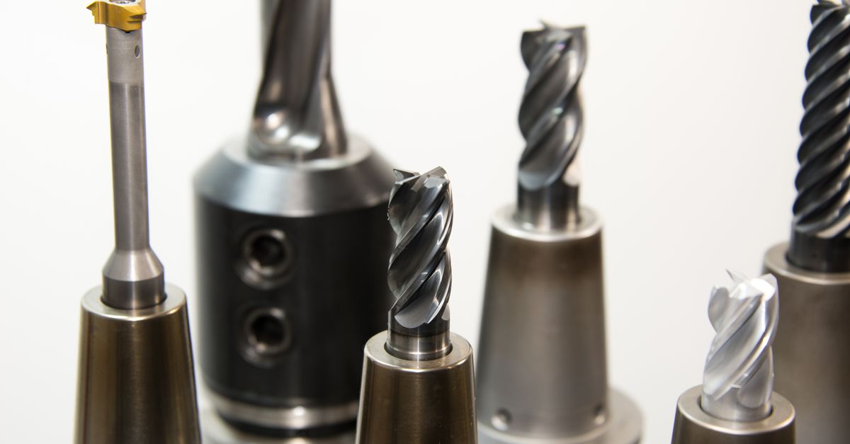
A face mill and a shell mill are not an either/or choice: "face mill" names what the cutter does (it machines a flat face), while "shell mill" names how it mounts (a central bore slips over an arbor or shell mill holder). Most indexable face mills are in fact shell-style bodies, so the two decisions that actually matter are lead angle (45° vs 90°) and mounting (shell vs integral). On lead angle: a 45° edge thins the chip to 71% of programmed feed — requiring a 1.4× feed compensation — and balances radial and axial cutting forces while reducing radial load compared with a 90° cutter, which takes full-thickness chips and machines true square shoulders. On mounting: a shell (bore-on-arbor) body can share compatible face-mill arbors within the same bore/pilot size, reducing holder inventory when a shop standardizes on common arbor sizes, while an integral body mounts directly for slightly higher rigidity.
For a complete overview of cutting tool types, grades, and coatings, see the cutting tools complete guide.
Two Words on Two Different Axes
"Face mill" and "shell mill" are not competing categories: face mill is a functional term (a cutter that machines a flat face), while shell mill is a mounting term (a bored body that slips over an arbor). The two axes are orthogonal — a single cutter is usually both at once, which is why a shell-type face mill is the most common indexable face-milling cutter. Treating them as either/or is a category error; the genuine choices are lead angle (Section 02) and mounting style (Section 04).
Face Mill (a function): A milling cutter with inserts positioned primarily on the face (bottom) of the body, cutting mainly on the axial face with minor radial engagement, typically at a 45° or near-90° lead angle. Its counterparts on the function axis are square and ball end mills — not shell mills.
Shell Mill (a mounting style): A cutter body with a central bore and keyway that mounts on a shell mill arbor or face mill holder, driven by a cross-key and pulled up by a central bolt. Its counterpart on the mounting axis is the integral-shank cutter. A shell body can carry face-milling or shoulder-milling geometry, and a compatible arbor can accept multiple cutter bodies sharing the same bore/pilot size.
| Cutting geometry | Shell-mounted (bore + arbor) | Integral (direct mount) |
|---|---|---|
| Face milling | Shell-type face mill (most common) | Integral face mill |
| Shoulder / end milling | Shell end mill | Solid end mill |
Pick the cutting geometry first (Section 02), then decide how it mounts (Section 04). ISO 6462 standardizes key dimensions for indexable face- and shoulder-milling cutter bodies; confirm the matching arbor pilot, key drive, and bolt dimensions on the maker's drawing.
Decision 1 — Lead Angle: 45° vs 90°
A 45° lead angle balances radial and axial cutting forces — lowering radial load versus a 90° cutter — and thins the chip to 71% of programmed feed, while a 90° lead angle produces near-zero axial force and full-thickness chips for shoulder milling. The lead angle is typically the most consequential geometric difference between cutter types, and it applies whether the body is shell-mounted or integral.
| Lead Angle | Axial Force | Radial Force | Chip Thickness | Best For |
|---|---|---|---|---|
| 45 degrees | ~71% of resultant (higher than 90°) | ~71% of resultant (lower than 90°) | ~71% of fz | General face milling, thin-wall parts |
| 75 degrees | Low (26% of total) | High (97% of total) | ~97% of fz (barely thinner) | Special-purpose (cast iron, short-chip), more axial depth than 45° |
| 90 degrees | Near-zero | High (100%) | 100% of fz (full) | Shoulder milling, deep axial cuts |
| Round insert | Variable (lead ~10–30°) | Variable | Progressive (~17–50% of fz) | High-feed milling, ramping |
✦ 45-Degree Lead Angle
- Balances axial and radial force, lowering radial load on the part vs a 90° cutter
- Reduces tendency to vibrate on thin or poorly clamped parts
- Produces thinner chips at same feed per tooth (smoother entry)
- Excellent surface finish with wiper inserts
✦ 90-Degree Lead Angle
- Full depth of cut capability (no chip thinning)
- Can machine shoulders and steps
- True 90-degree walls without secondary operations
- Better for slotting and pocketing operations
Chip Thinning Compensation
A 45-degree lead angle thins the chip to 71% of the programmed feed per tooth. To maintain the same material removal rate, increase feed per tooth by 1.4x. Failure to compensate means you are under-feeding, which accelerates flank wear from rubbing instead of cutting.
Surface Finish Comparison
Under stable finishing conditions, one or two wiper inserts on a 45° face mill can reduce typical surface roughness from around Ra 1.6-3.2 µm toward Ra 0.4-0.8 µm in a single pass — when cutter runout, insert height, feed per revolution, and wiper-flat width are controlled. Surface finish depends on lead angle, insert nose geometry, and wiper presence.
Wiper inserts are inserts with a flat secondary cutting edge (wiper flat) that trails behind the main cutting edge, smoothing the surface. One or two wiper inserts in a face mill body can reduce surface roughness from around Ra 3.2 toward Ra 0.4 when feed per revolution stays below the wiper-flat length.
| Configuration | Typical Ra (um) | Notes |
|---|---|---|
| 45-degree face mill, no wiper | 1.6-3.2 | Standard finish |
| 45-degree face mill, with wiper | 0.4-0.8 | Near-ground finish |
| 90-degree face mill, no wiper | 2.4-4.8 | Scallop marks visible |
| 75-degree face mill, no wiper | 2.0-4.0 | Between 45° and 90° |
A 90° face mill without wiper inserts typically produces Ra 2.4–4.8 µm — one to two grades rougher than a 45° mill at the same parameters — because the square entry angle leaves a more pronounced scallop pattern between feed passes.
Wiper Insert Limitations
Wiper inserts only work correctly when feed per revolution is less than the wiper flat length (typically 1.5–3.0 mm). At higher feeds, the wiper flat cannot cover the previous scallop and the benefit is lost. Also, using more than two wiper inserts can generate excessive cutting forces and cause vibration on long-overhang setups.
Decision 2 — Mounting: Shell (Arbor) vs Integral
Once the cutting geometry is set, choose the mounting style: a shell body on a shared arbor when one holder must serve several diameters, or an integral direct-mount body when rigidity on a single diameter outweighs modularity. Mounting is independent of lead angle — a 45° or a 90° cutter can be either shell-mounted or integral.
Choose a shell-mounted body when:
- Several cutter bodies of the same bore/pilot size must share fewer holders (one compatible arbor serves them all)
- Tool-magazine or storage space is limited (store compact bodies separately from arbors)
- The shop already runs arbor-based horizontal machining centers
- Diameters fall in the typical 40-160mm shell range
- Budget favors one arbor investment over a dedicated holder per diameter
Choose an integral (direct-mount) body when:
- One diameter runs often enough to justify a dedicated body
- Rigidity is the priority — no arbor interface in the load path
- Quick spindle changes matter more than diameter modularity
- Very large diameters (above the common shell range) where integral construction is standard
Insert Economy and Cutter Body Cost
A 160 mm cutter typically carries 10-16 inserts versus 4-8 inserts on an 80 mm cutter, raising metal removal rate but also raising body cost and per-change insert spend by roughly 2x. That difference is driven by diameter, not by mounting — a shell-mounted body adds a separate one-time arbor cost on top.
| Factor | Large Cutter (160mm) | Small Cutter (80mm) |
|---|---|---|
| Body Cost | $300–800 (typical) | $100–300 (typical) |
| Insert Count | 10-16 | 4-8 |
| Metal Removal Rate | ~1.5–2× higher at same fz and ap | Moderate baseline |
| Insert Cost per Edge | Same (standard ISO inserts) | Same |
On mounting cost: a shell-mounted body needs an arbor or shell mill holder ($80-200 per arbor), but that arbor is shared across every cutter body of the same bore/pilot size — so the per-body cost falls as the shop standardizes on common arbor sizes. An integral body folds the mount into the cutter, with no separate arbor to buy but a dedicated holder taper per cutter.
Quick Face Mill and Shell Mill Selection by Application
Use this matrix to map common face/shoulder-milling scenarios to a cutter family, entry angle, and insert configuration — confirm against your spindle taper, fixture rigidity, and finish target.
| Scenario | Mill Type | Entry Angle | Insert Style | Why |
|---|---|---|---|---|
| Large flat surface, demanding finish (>100 mm cuts) | 45° face-milling cutter | 45° | Standard inserts + 1-2 wiper inserts | 45° lead balances cutting forces (lower radial than 90°) and wiper flats deliver Ra 0.4-0.8 µm under stable conditions |
| Thin-walled or poorly clamped parts | 45° face-milling cutter | 45° | Standard inserts, no wipers | Lower radial force than a 90° cutter reduces sideways push on the wall, limiting chatter |
| Square shoulders, true 90° walls in one pass | 90° face/shoulder cutter | 90° | Square or rectangular inserts | 90° entry produces full-thickness chips and a vertical wall, eliminating a secondary finishing operation |
| Slotting and pocketing on a vertical mill | 90° shoulder cutter (shell or integral) | 90° | Square inserts | Full axial depth-of-cut capability without chip thinning compensation lets the cutter clear a full-width slot |
| Multi-diameter shop, limited arbor budget (40-160 mm) | Shell-mounted body on a shared compatible arbor | 45° or 90° | Standard ISO inserts | One compatible arbor accepts multiple cutter bodies of the same bore/pilot size, cutting holder inventory cost roughly in half |
| High-feed roughing in steel and cast iron | Round-insert face mill | Effective lead ~10-30° | Round inserts | Progressive chip thickness lets feed per tooth climb 2-3x while spreading load over a larger contact arc |
| Aluminum face milling, very high RPM | 45° face mill, polished body | 45° | PCD or polished carbide inserts | Polished flutes prevent built-up edge from low-melting aluminum welding to the cutting face |
| Cast iron face milling with abrasive wear | 45° or 75° face mill | 45° / 75° | Ceramic or coated carbide inserts | Higher heat resistance copes with discontinuous chips and abrasive carbide inclusions in iron |
Selection Summary
A 45° face mill with wiper inserts is the default choice for flat-surface finishing above 100 mm — under stable conditions it typically delivers Ra 0.4–0.8 µm in a single pass while keeping radial load low by balancing cutting forces. A shell-mounted body is the better choice when one compatible arbor must serve several cutter bodies of the same bore/pilot size, letting you swap bodies without buying a new holder for each diameter.
The 75° lead angle offers minimal chip-thinning benefit (~97% of fz) and is best treated as a special-purpose face-milling angle — cast iron and short-chipping materials, where it keeps better edge strength than 90° — not as a general compromise between 45° and 90°.
For an overview of the broader catalog of milling cutters, drills, and reamers across the lineup, see the 2026 cutting tool line refresh.
Match cutter type to your primary operation and mounting system.
For dedicated face milling of large surfaces with demanding finish requirements, a 45-degree face mill with wiper inserts delivers the best combination of productivity and surface quality. For versatile shops needing multiple diameters with minimal arbor investment, a shell-mounted body provides modular economy. Use 90-degree cutters when shoulder milling or full-depth axial cutting is required. Compensate feed per tooth by 1.4× when using 45-degree lead angles to maintain target material removal rate.
What surface finish can a 45-degree face mill with wiper inserts achieve?
A 45° face mill with wiper inserts can typically achieve Ra 0.4-0.8 µm — approaching a ground finish — in a single pass under stable conditions (controlled runout, insert height, and feed per revolution). Without wipers, the same cutter produces Ra 1.6-3.2 µm in typical steel and aluminum. Wiper flat length must exceed feed per revolution, or the benefit is lost.
Why do I need to compensate feed rate with a 45-degree lead angle?
A 45° lead angle thins the chip to 71% of the programmed feed per tooth, so the cutter under-feeds at the nominal rate. Increase feed per tooth by 1.4× (reciprocal of 0.707) to maintain the target material removal rate. Without this compensation, the tool rubs instead of cutting, accelerating flank wear — especially in steel and cast iron.
Is a shell mill better than a face mill?
Neither is "better" — they describe different things. "Face mill" is the cutting function (machining a flat face); "shell mill" is the mounting (a bored body on an arbor), and most face mills are themselves shell-mounted. The real mounting choice is shell versus integral: a shell body shares one compatible arbor across cutter bodies of the same bore/pilot size (within the 40-160 mm range), cutting holder inventory roughly in half, while an integral body offers slightly higher rigidity.
When should I choose a 90-degree cutter instead of a 45-degree face mill?
Choose a 90° cutter when you need to machine shoulders, steps, or pockets with true 90° walls in a single pass, or when a typical full axial depth of cut (10-15 mm) is required without chip-thinning compensation. A 45° mill cannot form a square shoulder; it leaves a chamfer on the vertical wall that requires a secondary operation.