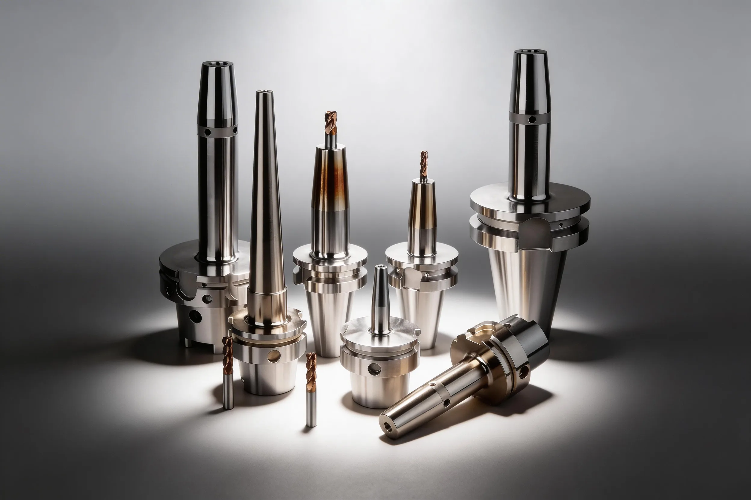
In high-mix CNC production, unplanned tool changes consume 12–20% of available spindle time — and the majority trace back to three solvable failures: tools loaded without verified offsets, no tracked life limits, and no pre-staged replacement tool. Integrating an offline presetter, a simple tool life database, and a sister tool protocol reduces unplanned stops by 60–80% in most job-shop environments within 90 days of deployment.
Quick Tool Management Reference
| Problem / Goal | Primary Action | Expected Impact |
|---|---|---|
| Offset entry errors cause first-part scrap | Measure all tools offline on presetter; transfer via DNC/USB | Eliminates manual offset entry; scrap-on-first-part drops to near zero |
| Unplanned tool failure mid-cycle | Set life limits at 80% of tested tool life; trigger sister tool swap | Unplanned stops cut by 60–80% in typical job-shop settings |
| No visibility into which tools are near end-of-life | Run a shared tool life spreadsheet or TMS with counts per spindle | Shift-end review takes under 5 min; catches 90% of at-risk tools before next run |
| Setup time too long between jobs | Pre-stage sister tools as designated offline backup assemblies | Sister tool swap adds ≤2 min vs. 15–45 min for emergency re-setup |
| High-mix changeover causes offset confusion | Use ISO 13399 tool data format to link presetter data to CNC directly | Removes manual re-entry across job changeovers; compatible with most modern CNCs |
Why Tool Management Breaks Down in High-Mix Production
In high-mix production, the per-tool amortization model breaks down because no single tool runs long enough for informal tracking to work. A low-mix shop with 8 active jobs can track tool condition by feel and experience; a shop running 40–80 active jobs cannot.
The three root causes of unplanned downtime in high-mix CNC environments are (see also: CNC Tool Wear Monitoring for sensor-based wear detection and CNC Machining Optimization for speed and feed selection):
-
Offset entry errors — Operators measure tools at the machine with a tool-touch-off probe, write the result on paper, and type it manually into the offset register. Even a single transposed digit (e.g., 52.31 mm vs. 53.21 mm) causes a bad first part or a tool crash.
-
No life limit enforcement — Tools are replaced when they visually look worn or when a part fails inspection, not at a consistent, predictable interval. The actual tool life per insert or cutting edge is never recorded, so the next setup starts from zero knowledge.
-
No pre-staged replacement — When a tool does fail, the operator must find a replacement insert, pick the correct grade, assemble the holder, measure offsets, and re-enter data. That emergency sequence typically takes 15–45 minutes per tool failure.
Shops that address all three root causes simultaneously reduce tool-related downtime by 60–80% — shops that address only one typically see a 20–30% improvement at best. The order of implementation matters: presetter first (eliminates offset errors), life tracking second (enables prediction), sister tools third (provides the response capacity to act on predictions).
Offline Presetter Integration
An offline presetter measures tool assemblies — holder + insert/cutting tool — before they go to the machine, so no measurement time is consumed at the spindle.
A properly integrated presetter reduces per-tool setup time from 3–8 minutes (at-machine) to under 30 seconds (transfer), while raising offset accuracy from ±0.02–0.05 mm (manual entry) to ±0.001–0.003 mm (presetter-grade).
Presetter Types and Selection
| Presetter Type | Repeatability | Best Application |
|---|---|---|
| Mechanical (comparator-type) | ±0.010 mm | Light-duty shops, ≤20 tools/shift |
| Optical bench (non-contact) | ±0.003–0.005 mm | General CNC turning/milling |
| Vision-based (Zoller, BIG DAISHOWA) | ±0.001–0.002 mm | High-precision, ≤0.01 mm tolerance work |
For most high-mix job shops, an optical bench presetter with ±0.003–0.005 mm repeatability hits the sweet spot between cost ($8,000–$25,000) and accuracy requirements for tolerances down to ±0.02 mm.
Data Transfer: From Presetter to CNC
The three transfer methods, in order of reliability:
-
DNC (Direct Numerical Control) network link — Presetter software writes offset data directly to the CNC control via Ethernet or RS-232. Fanuc, Mitsubishi, and Mazatrol controllers all support this. Zero manual transcription.
-
USB/SD card file transfer — Presetter exports a formatted offset file (CSV, XML, or proprietary format); operator loads it at the CNC. One deliberate file-load step still occurs, but offset values are transferred exactly as measured.
-
ISO 13399 tool data format — The standard that encodes tool assembly geometry, offsets, and assembly data in a machine-readable XML structure. ISO 13399 is used when passing tool data between presetter software and CAM systems, or when managing tools across multiple CNCs with different controls. Major presetters (Zoller, BIG DAISHOWA, Speroni) and CAM platforms (Mastercam, Siemens NX, CATIA) support ISO 13399 natively; it removes re-entry entirely for shops with compatible infrastructure.
Best Practice: The "Sealed Assembly" Rule
Once a tool assembly is measured on the presetter, treat it as sealed — no further adjustments at the machine until the tool reaches its life limit. If an operator adjusts an offset at the CNC, that adjustment must be fed back to the presetter record for the next setup. Without this feedback loop, the presetter database drifts from actual shop state within 2–3 shifts.
Presetter ROI Calculation
At a conservative 4 tools per job change and 3-minute at-machine setup per tool, a single job changeover consumes 12 minutes of spindle time for setup alone. At $80/hour machine rate, that's $16 in lost capacity per changeover. A shop running 8 changeovers per day generates $128/day in offset-related setup cost — roughly $32,000/year. A $15,000 presetter pays for itself in under 6 months when setup time drops by 70% or more.
Tool Life Tracking: Building a Usable Database
Tool life tracking fails in high-mix shops not because the concept is wrong, but because the tracking systems require more effort to maintain than the time they save. The minimum viable tracking system is a single shared spreadsheet, not enterprise TMS software.
The Minimum Viable Tool Life Database
A five-column spreadsheet is sufficient for shops running up to 50 active tool types:
| Column | What to Record |
|---|---|
| Tool ID | Unique ID per assembly (e.g., T01, EM-6mm-coated) |
| Operation | Job and operation number where tool runs |
| Life Limit (parts/minutes) | Target replacement interval — set at 80% of first-failure point |
| Current Count | Cumulative parts or minutes cut since last insert change |
| Status | Active / Near limit (>70%) / Replace-next-setup |
The 80% life limit rule is the most important column: by retiring tools at 80% of their tested first-failure point, shops substantially reduce the risk of catastrophic failures (sudden edge fracture, hole-to-hole diameter drift, surface finish step change) that generate scrap and require emergency re-setup.
Setting Initial Life Limits
The most practical method for a new tool or new material combination is the staircase method:
- Run the first tool to visible wear (flank wear VB_B ≈ 0.3 mm per ISO 3685, or first-part reject, whichever comes first). Record the part count at that point as T_max.
- Run 3–5 more tools of the same type to confirm T_max. Calculate the mean and standard deviation.
- Set the working life limit at mean T_max × 0.80. If standard deviation is >15% of mean, use 70% instead.
Per ISO 3685:1993, the standard flank wear criterion for finishing operations is VB_B = 0.3 mm (average flank wear in zone B). For roughing or interrupted cuts, the maximum flank wear limit extends to VB_B max = 0.6 mm before structural tool integrity is at risk.
For most carbide insert turning operations in steel, tool life falls in the 20–80 parts per edge range at recommended cutting speeds — establishing this baseline takes one shift of deliberate observation, not weeks of data collection.
Integrating Life Counts with the CNC
Most Fanuc-series controls support M-code triggered tool life counters (for a broader overview of tool holding systems and their setup, see The Complete Guide to Tool Holding) (G10 offset management with tool life data in the offset table). The control increments the tool life counter by one per M-code call and flags the tool as expired when the limit is reached. When using this feature:
- Pair the counter with a T+1 sister tool call (see Section 04) so the control automatically selects the replacement without operator intervention.
- Set the warning threshold at 90% of limit to give the operator one full cycle of notice before the swap is forced.
- Reset the counter only when a confirmed insert change has occurred — not as a quick override.
Do Not Reset Counters Without Replacing the Insert
Resetting a tool life counter without changing the insert is the leading cause of edge fractures in shops that use life tracking. Empirical wear-vs-time curves measured per ISO 3685 show a steep tertiary phase after initial wear and steady-state wear stages — beyond the verified life limit, flank and crater wear approach the structural integrity limit of the edge, and an insert can fracture suddenly even when surface appearance looks acceptable. An expired insert that "looks okay" is the highest scrap-risk tool in the shop.
Sister Tool Strategy for High-Mix Production
A sister tool is a pre-measured, pre-staged duplicate of a running tool assembly, designated as its automatic replacement when the primary tool reaches its life limit. Sister tools convert a 15–45 minute emergency re-setup into a 1–2 minute programmed exchange.
When to Use Sister Tools vs. On-Demand Replacement
| Production Scenario | Preferred Strategy |
|---|---|
| High-volume, repeat operations (>100 parts/run) | Sister tools always — stops are expensive |
| High-mix, short run (5–25 parts/job) | Sister tools for critical operations (tight-tolerance, long-cycle) only |
| One-off prototype or first article | On-demand replacement — sister tool setup cost exceeds benefit |
| Unmanned overnight runs | Sister tools mandatory — no operator available to respond |
In high-mix production, sister tools should cover only the top 20% of tools by downtime risk — typically the tools on the longest cycle-time operations or the tightest-tolerance features. Adding sister tools to every tool in the magazine creates more complexity than it saves.
Sister Tool Assignment Logic
The CNC control references sister tools by assigning a tool group number rather than a fixed pocket number. Both the primary and sister tool share the same group ID; the control selects whichever is still within its life limit.
For Fanuc controls, the standard implementation:
- T0101 (primary) and T0102 (sister) share group G01
- When T0101 life count expires, the control selects T0102 automatically at the next T-call
- T0102 must have its own offset register loaded with the presetter-measured values for that specific sister assembly
The critical rule is that each sister tool must be independently measured on the presetter — never copy offsets from the primary tool, because even nominally identical assemblies differ by ±0.003–0.010 mm in actual projection length.
Stocking Logic for Sister Tools
A practical sister tool inventory formula:
Sister tool slots needed = (Longest production run in parts) ÷ (Tool life limit in parts) × (Number of critical tools) × 1.5 safety factor
Example: A job running 200 parts uses a 6mm end mill with a 50-part life limit. The 200/50 = 4 tool lifetimes consumed across the run translate into 3 planned swaps (the first tool runs out at part 50, the next at 100, the last at 150). With one sister tool loaded, the control handles the first swap automatically; the operator handles the remaining two at planned intervals. The 1.5× safety factor in the formula above covers life variation and the occasional tool that fails slightly early, suggesting 4–5 pre-staged slots for high-confidence unmanned running.
Implementation Sequence: 90-Day Rollout
Rollout Principle
Do not try to implement presetter, life tracking, and sister tools simultaneously across all tools. Start with the three highest-impact tools (longest cycle time + highest scrap cost if they fail) and prove the system before scaling.
Week 1–2: Baseline measurement
- Identify the top 10 tools by downtime cost (cycle time × failure frequency)
- Record current at-machine setup times and offset accuracy errors
- Set the target: 70% reduction in offset entry scrap, 60% reduction in unplanned tool stops
Week 3–4: Presetter commissioning
- Qualify the presetter: measure a known reference tool 10 times and verify repeatability ≤±0.005 mm
- Establish a DNC link or USB transfer protocol for the target CNCs
- Train operators on the sealed assembly rule — no at-machine fine-tuning of presetter-set tools
Week 5–8: Life database go-live
- Run the first 5 tools through the staircase life limit method
- Enter initial limits at 70% of observed T_max as a conservative start
- Adjust upward by 5–10% per tool after 3 confirmed cycles with no failures
Week 9–12: Sister tool deployment
- Pre-stage sister assemblies for the 3 highest-downtime-risk tools
- Measure each sister assembly on the presetter and load offsets independently
- Verify automatic tool group switching on the CNC before the first production run
Summary
Presetter + life limits + sister tools is the complete system.
Presetter integration eliminates offset entry as a scrap source. Tool life tracking converts failure from a surprise event into a scheduled exchange. Sister tools provide the physical response capacity to execute that exchange without spindle stops. Implement in that sequence — presetter first, then life tracking, then sister tools — and target the top 20% of tools by downtime risk before scaling to the full magazine.
Shops that deploy all three components in a structured 90-day rollout consistently achieve 60–80% reductions in unplanned tool-related downtime. The investment (presetter + tracking overhead + sister tool inventory carrying cost) pays back within 6–12 months in most high-mix job-shop environments operating 2+ shifts.
Sources
- ISO 3685:1993 — Tool-life testing with single-point turning tools
- ISO 13399:2023 — Cutting tool representation and exchange of data
- Zoller — Presetter and tool management systems
- Sandvik Coromant — Tool management guide
- Fanuc — Tool life management parameter guide (Series 0i Operator Manual)
- Machinery's Handbook 31st Edition — Tool life and wear criteria (pp. 1196–1200)
What is a sister tool in CNC machining?
A sister tool is a pre-measured duplicate of a running tool assembly stored in the magazine as the automatic replacement when the primary tool reaches its life limit. When the CNC control detects the life count expiry, it selects the sister tool at the next T-call — converting a 15–45 minute emergency re-setup into a 1–2 minute programmed exchange.
How does an offline presetter improve CNC accuracy?
An offline presetter measures tool assemblies outside the machine before setup, transferring offsets via DNC or USB with repeatability of ±0.001–0.005 mm — compared to ±0.02–0.05 mm for manual entry at the machine. This eliminates transposition errors and reduces scrap-on-first-part to near zero for shops running more than 8 changeovers per day.
What tool life limit should I set in my CNC control?
Set the tool life limit at 80% of the tested first-failure point (T_max), determined by running 3–5 tools of the same type to the ISO 3685 flank wear criterion of VB_B = 0.3 mm or first-part reject. If tool-to-tool life variability is high (standard deviation >15% of mean), use 70% instead. Retire at the limit — resetting counters without replacing the insert is the leading cause of catastrophic edge fractures.
When does a high-mix shop need sister tools?
Use sister tools for the top 20% of tools by downtime risk — typically the tools running on your longest-cycle-time or tightest-tolerance operations. For operations with ≤25 parts per run, sister tool setup cost generally exceeds the benefit unless the operation is unmanned. For overnight lights-out runs, sister tools are mandatory for all critical tools regardless of job quantity.
What is ISO 13399 and why does it matter for tool management?
ISO 13399 is the international standard defining a machine-readable XML format for encoding cutting tool geometry, assembly data, and offsets. It matters for tool management because it enables presetters, CAM systems, and CNC controls from different manufacturers to exchange tool data without manual re-entry — eliminating offset transcription errors across job changeovers in multi-machine environments.